30 AGL50-EV
[51] Contactor TRUE when the Run contactor has to be closed, either for upward or downward motion.
[52] Contactor UP TRUE when the Run contactor for upward motion has to be closed.
[53] Contactor DOWN TRUE when the Run contactor for downward motion has to be closed.
[54] Brake cont TRUE when the mechanical brake has to be released.
[55] Lift start TRUE when the inverter output bridge is operating and no DC injection is being operated.
[78] Timer 1 out TRUE when the Timer function output is 1.
7.2.2 Speed indication
At power-on the drive keypad shows the speed of the lift car (parameter d.007), expressed in mm/s. Likewise, all the
variables related to the speed of the motor (d.008, d.302) are expressed in mm/s. The conversion between electrical Hz
and car speed is automatically performed by the drive, as explained in the following chapter. The conversion ratio can
also be overwritten by the user, by setting parameter P.600.
The parameter to be shown at power-on can be congured by setting the parameter P.580.
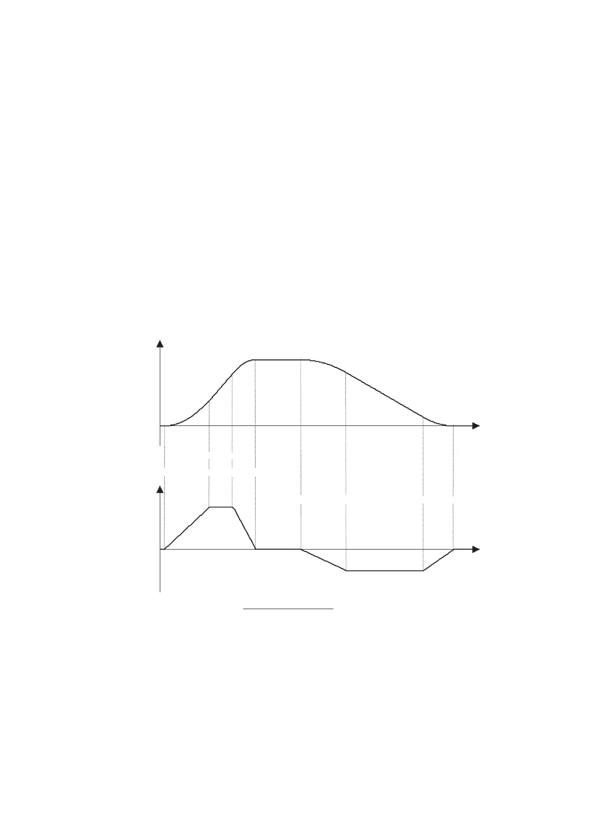
7.3 Ramp Function
Four independent jerks are available for each prole, together with linear acceleration and deceleration times. All prole
parameters are expressed in terms of car linear quantities. The equivalence between car speed v(m/s) and inverter output
frequency f(Hz) is automatically performed by the drive, based on the value of the following parameters:
- f
b
: S.101 Base frequency (Hz)
- v
N
: S.180 Car max speed (m/s)
The ramp prole is shown in Fig.6. Prole number 1 has been used as an example, but the same applies to all the four
available proles. The increase or decrease of the jerk values causes the increase or decrease of the running comfort.
Motor speed
D.007 Output speed
Acceleration
S.230-Jerk acc ini 1
S.231-Acceleration 1
S.232-Jerk acc end 1
S.233-Jerk dec ini 1 S.235-Jerk dec end 1
S.234-Deceleration 1
Fig.7.4 – Lift ramp prole
7.3.1 Space calculation and acceleration / deceleration ramps settings
The space covered by the lift car during acceleration and deceleration ramps can be calculated off-line by the drive, by
executing the command: C.060 Calculate space . The results of the calculation can be monitored into the parameters:
d.500 Lift space space covered by the lift car (expressed in meters) when accelerating from zero to the
maximum speed (dened by S.180) and then immediately decelerating back to zero(one
oor travel)
d.501 Lift accel space space covered by the lift car (expressed in meters) when accelerating from zero to the
maximum speed (dened by S.180).
d.502 Lift decel space pace covered by the lift car (expressed in meters) when decelerating from the maximum
speed (dened by S.180) to zero.
Knowing the space needed to accelerate and decelerate the lift car with the ramp set in use, is useful to determine
whether the ramps are compatible with the position of the oor sensors before actually starting the drive. For example,

 Loading...


