16 AGL50-EV
Ground connection to both sides of the cable shield (AC motor)
The shield of the supply cable of the AC motors must be grounded on both sides in order to obtain 360° contact, that
means the whole shield. This can be accomplished using suitable metallic EMC cables press grounded at a full 360° at
the input of the cabinet and of the motor’s terminal strip. If this connection is not possible, the shielded cables should
be brought inside the cabinet and connected with an omega connector to the mounting panel. The same must be done
on the motor side. In case a 360° connection on the motor’s terminal strip is not possible, the shield must be grounded
before entering into the terminal strip. This should be done on the metal support of the motor, using an omega connector
(see gure). In case a metal duct has to be used, it should be grounded at a full 360° where possible.
Pigtail avoidence
While grounding the shieldes of the cables, one has to use a 360° connection (E.g.: omega bus as in the gure 4.2) with
a pigtail connection to be absolutely avoided. By pigtail is meant the connection to earth ground of the cable shield by
means of an additional wire.
Direct connection between the ground bus and motor chassis
Independently from ground-connection of the motor’s chassis, it must always be connected to the ground wire (yellow/
green) coming from the panel ground bus.
Max length of the AC motor’s cables inside the cabinet
From the grounding of the screen side cabinet of the inverter terminal strip, the supply’s cables have to measure 5 meters
(16.4 feet) maximum.
Mounting sequence for EMI-... lters with inverter
In case of inverters, these lters have to be serie-connected between the inverter and the AC mains. The connection
between the lter and inverter’s terminals must be done with a four poles cable, whose max.length is 30 cm. (12 inches).
If that connection is longer, the cable must be shielded.
Grounding of EMI-... lters with inverter
The yellow/green ground wire of the four poles cable must be connected on one side directly to one of the two gounding
terminals of the inverter, the other side to one of the two lters grounding terminals. The other grounding terminal of the
lter must be brought directly to the grounding bus of the cabinet.
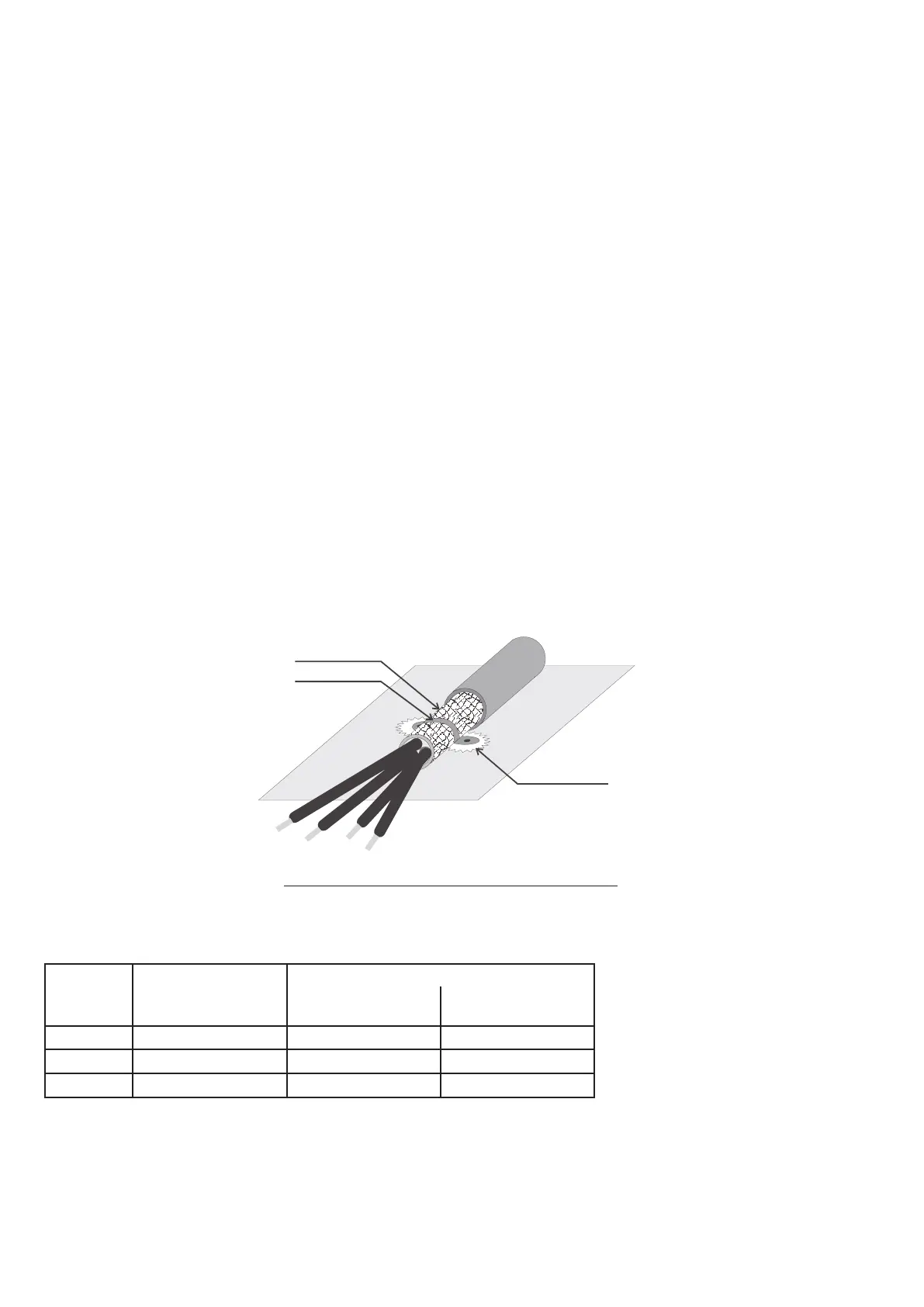
Schermo/Shield
Connettore Omega
Omega connector
Area non verniciata
Not painted area
Pannello di fissaggio
Mounting panel
Figura 4.2.OMEGA plug: grounding 360° of a shielded cable.
4.3 Cooling fans
No connection is required, the internal fans are power supplied by an internal circuit.
Sizes Heat dissipation) Fan capacity
[W]
Heat sink
[m
3
/h]
Internal
[m
3
/h]
2040 180 20 -
2055 205 2 x 20 -
2075 280 2 x 20 11

 Loading...


