AGL50-EV 19
4.6 Encoder Input
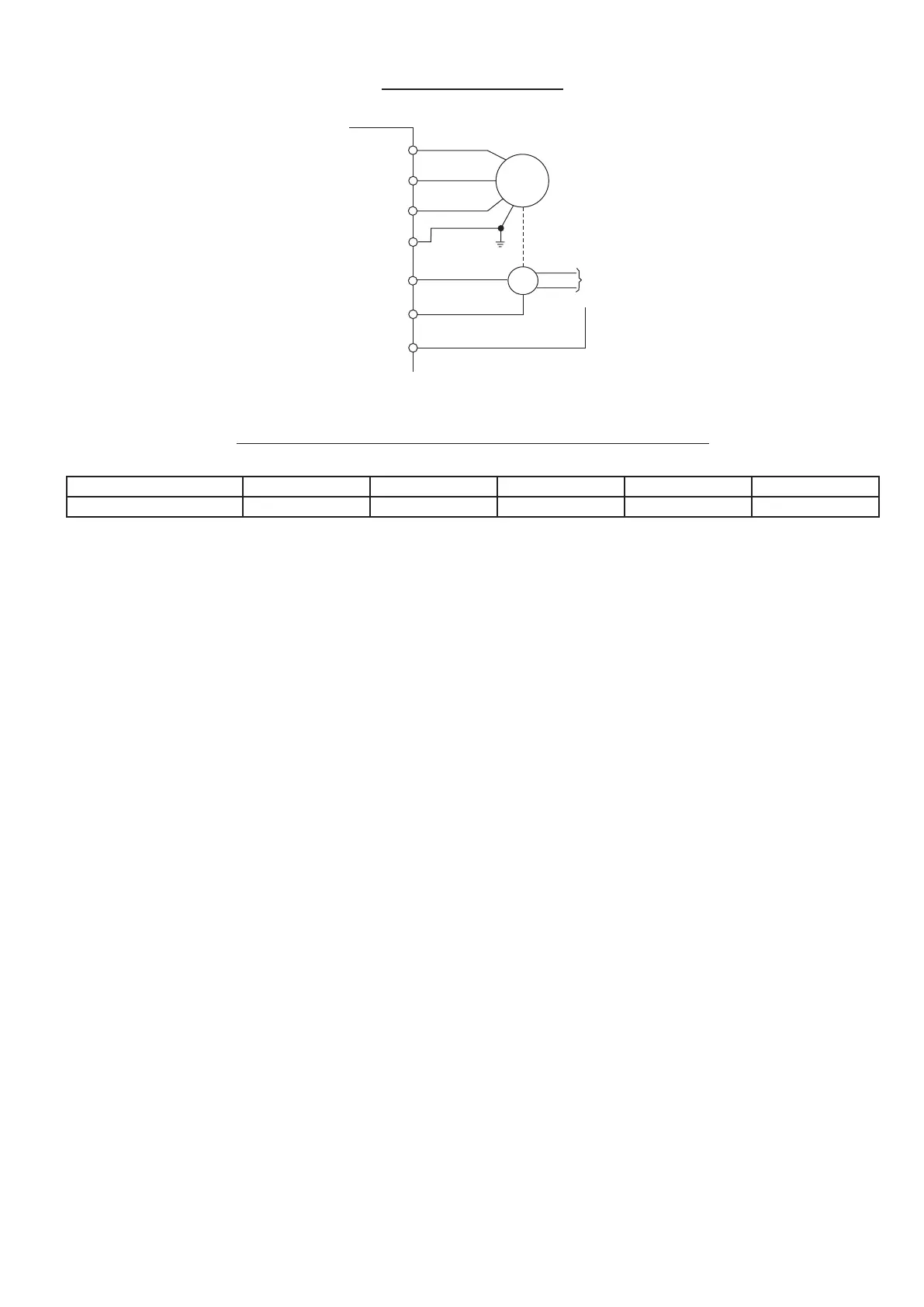
Figure 4.6.1: encoder connection
U2/T1
V2/T2
W2/T3
M
PE2
E
5
Digital Input 6
20
22
Channel A
Channel B
External
+24V
024V
COM
24
Table 4.6.1: Recommended Cable Section and Length for the Connection of Encoders
Cable section [mm
2
] 0.22 0.5 0.75 1 1.5
Max Length. m [feet] 27 [88] 62 [203] 93 [305] 125 [410] 150 [492]
Requirements:
Digital encoder:
• max frequency: 25 kHz (select the appropriate number of pulses depending on required max. speed)
• Channels :
- one-channel: A (one-channel complementary A-,NOT allowed)
- two-channel: A and B (two-channel complementary A- and B-, NOT allowed).
Encoder loss detection is not possible.
• Power supply: + 24V externally supplied.
• The digital inputs common (terminal 24) have to be rightly connected to the external supply:
- to 0 V of supplier, if the encoder is PNP type
- to + 24 V of supplier, if the encoder is NPN type.
Note!
If Digital input 5 and Digital input 6 are used as encoder input, I.004 and I.005 must be set to [0] None.
Than encoder feedback parametrizzation must be execute.

 Loading...


