20 AGL50-EV
5 - Drive Keypad Operation
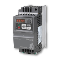
In this chapter the parameters management is described, by using the drive keypad.
5.1 Keypad
Changes made to parameter have immediate effect on drive operation, but are not automatically stored in
permanent memory. An explicit command is required to permanently store the parameters: “C.000 Save
parameters”.
Rev Fwd Limit AlarmPrg
Prg
Enter
Codice parametro
(Menu + numero da 000 a 999)
Menu:
d
S
I
=DISPLAY
=STARTUP
=INTERFACE
F
P
A
C
=FREQ & RAMPS
=PARAMETER
=APPLICATION
=COMMAND
Limit Alarm
Prg
Rev Fwd
Prg Scroll menù: Allows navigation thruogh the drive main menu (d.xxx, S.xxx, I.xxx, F.xxx, P.xxx, A.xxx and
C.xxx). Also used to exit the editing mode of a parameter without appling the changes.
E Enter key: Used to enter the editing mode of the selected parameter or to conrm the value.
▲ UP key: Used to scroll up through parameters or to increase numeric values while in editing mode; it can
also be used to increase motorpotentiometer reference value, when F.000 Motorpot ref parameter
is displayed (F, FREQ RAMP menu).
▼ DOWN key: Used to scroll down through parameters or to decrease numeric values while in editing mode; it
can also be used to decrease motorpotentiometer reference values, when F.000 Motorpot ref
parameter is displayed (F, FREQ RAMP menu).
I Start key: Used to START the drive via keypad; requirements:
+24V between 12 & 26 terminals (Enable)
+24 V between 14 & 26 terminals (Run Fwd) or + 24 V between 16 & 26 terminals (Run Rev)
P.000 Cmd source sel = [1] CtlWrd & kpd parameter setting
O Stop key: Used to STOP the drive via keypad;
Keypad LED’s meaning:
PRG (Yellow Led) Flashes if the parameters have not been permanently saved to memory.
REV (Green Led) Reverse running
FWD (Green Led) Clockwise motor rotation
Limit (Yellow Led) Inverter limit state
Alarm (Red Led) Inverter alarm state
Note!
The FWD LED lights up during the direct current injection phase (start and stop).

 Loading...


