ADL300 • Quick installation guide - Specifications and connection 19
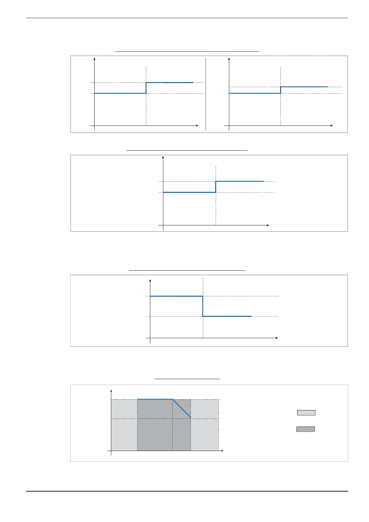
4.5.2 Derating values for switching frequency
The switching frequency is modied according to the temperature of the drive (measured on the heat sink), as shown in
the gure below.
Figure 4.5.2: Ratio between switching frequency/heat sink temperature
5
10
T diss (°C)
F (kHz)
SW
T diss th
4.5.3 Kalt: Ambient temperature reduction factor
Figure 4.5.3: Tamb reduction coefcient
Ta
T
-10 45 50
Function not allowed
Range of ambient temperatures allowed
4.6
Voltage level of the inverter for safe operations
The minimum time between the moment in which an ADL inverter is disabled from the mains and that in which an
operator can operate on internal parts of the inverter, without the danger of electric shock, is 5 minutes.
This value takes into account the time to turn off an inverter supplied at 460 Vac + 10%, without any options (time indicated for disabled
inverter condition).

 Loading...


