48 VDL200 • Quick installation guide - Specifications and connection
SEQ
02 PAR: 2102
Encoder supply
5.2 V
Def: 5.2
E
SEQ
02 PAR: 2102
Encoder supply
0000005.22 V
Def: 5.2
5.3 A
5.1 A
E
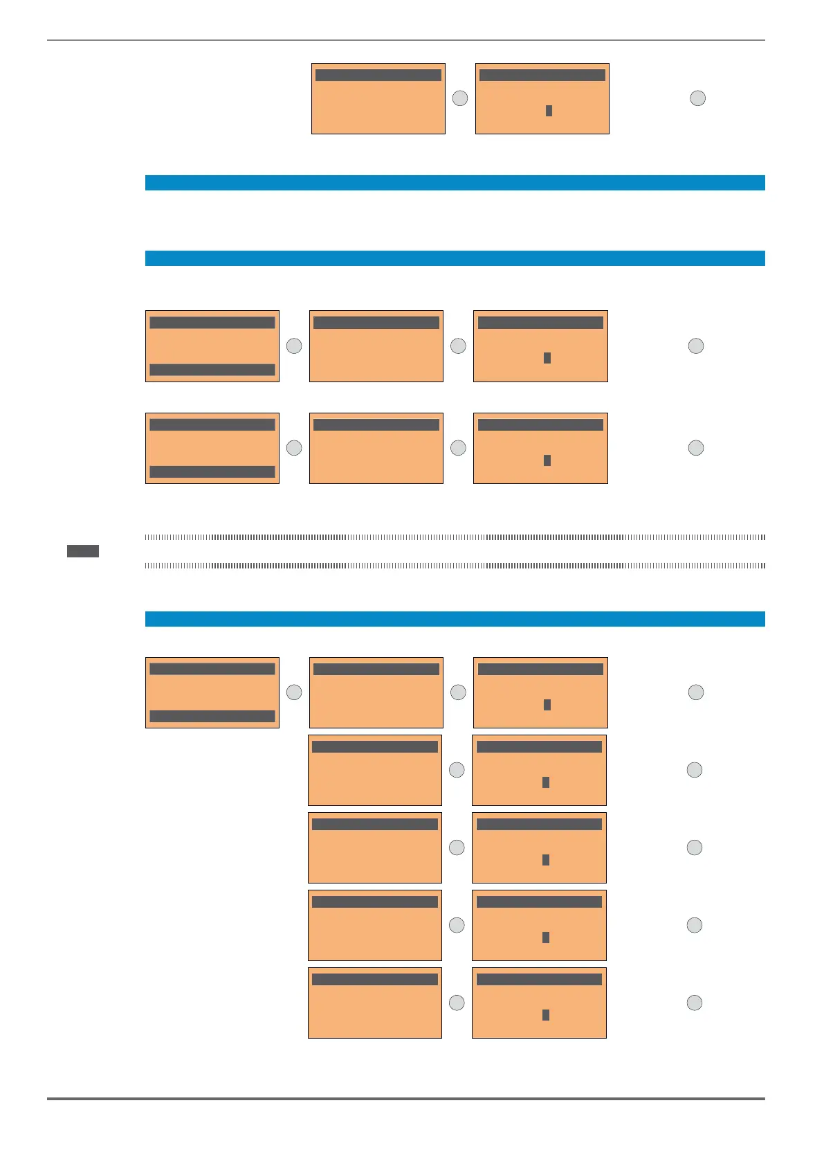
Step 5 – Encoder phasing
Not available in this mode.
Step 6 - Setting the maximum speed reference value and system speed
reached with each single reference signal (analog or digital).
03 STARTUP WIZARD
Set max motor speed?
E=Yes Down=Next
E
SEQ
01 PAR: 680
Full scale speed
1440 rpm
Def: 1440
E
SEQ
01 PAR: 680
Full scale speed
0000014400 rpm
Def: 1440
1441 rpm
1439 rpm
E
Set the maximum system speed in m/s
03 STARTUP WIZARD
Set max car speed?
E=Yes Down=Next
E
SEQ
01 PAR: 11006
System s
p
eed
1.0 m/s
Def: 1.0
E
SEQ
01 PAR: 11006
System s
p
eed
0000001.00 m/s
Def: 1.0
1.1 m/s
0.9 m/s
E
After setting the speed, proceed to step 7 to set the system weights.
Note! The factory (default) setting depends on the size of the drive that is connected. These values refer to the VDL200-1055.
Step 7 - Setting the system weights
The system weights must be entered in this part of the wizard procedure.
03 STARTUP WIZARD
Set system weights?
E=Yes Down=Next
E
SEQ
01 PAR: 11150
Weight of cabin
0 kg
Def: 0
E
SEQ
01 PAR: 11150
Weight of cabin
0000000000 kg
Def: 0
1 kg
0 kg
E
SEQ
02 PAR: 11152
Counterweight
0 kg
Def: 0
E
SEQ
02 PAR: 11152
Counterweight
0000000000 kg
Def: 0
1 kg
0 kg
E
SEQ
03 PAR: 11154
Max load weight
0 kg
Def: 0
E
SEQ
03 PAR: 11154
Max load weight
0000000000 kg
Def: 0
1 kg
0 kg
E
SEQ
04 PAR: 11156
Cable weight
0 kg
Def: 0
E
SEQ
04 PAR: 11156
Cable weight
0000000000 kg
Def: 0
1 kg
0 kg
E
SEQ
05 PAR: 11158
Reducer inertia
0 kgm²
Def: 0
E
SEQ
05 PAR: 11158
Reducer inertia
0000000000 kgm²
Def: 0
1 kgm²
0 kgm²
E

 Loading...


