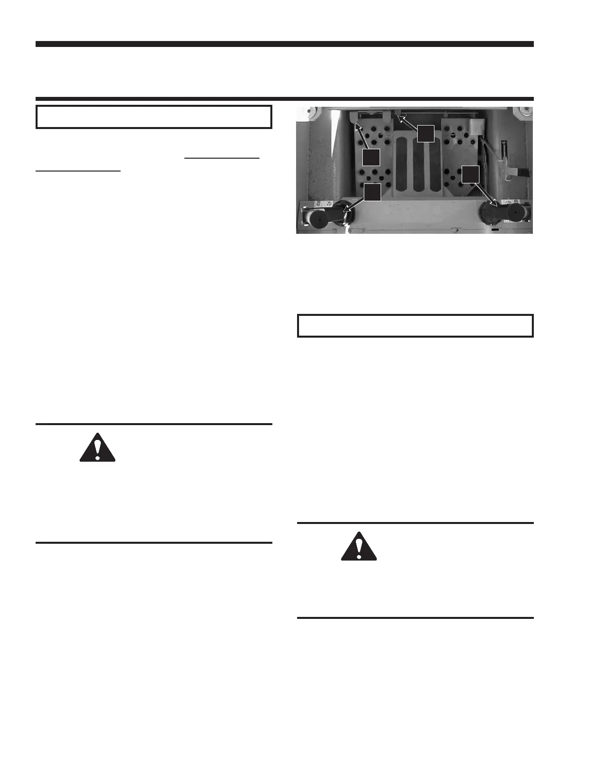
DUAL HAND CONTROLLED LOADERS (Fig. 5-5)
Handles with pivoting grips on the skid loader control the hydraulic and hydrostatic function. The right handle
controls the right side drive and the tilt. The left handle controls the left side drive and the lift.
Drive Control Handles
NOTE: Moving the handles equally in the same
direction will result in traveling straight forward
or
straight backward
.
Forward Travel: Push both handles straight forward,
slowly in the same direction.
Reverse Travel: Pull both handles straight backward,
slowly in the same direction.
Turning during Travel: Move one handle farther
forward or rearward than the other handle. Turn
direction is determined by which handle moves the
farthest forward; to turn left, move the right handle
farther forward than the left handle.
Fast Turning (Pivoting): Move the handles in opposite
direction of each other. The direction of travel is
determined by which handle is moved forward; the left
handle forward turns the loader to the right, the right
handle forward turns the loader to the left.
Auxiliary Hydraulics: Depress the foot pedal to
control the direction of flow. A stop locks the foot pedal
in the “on” (detent) position for continuous use.
WARNING
BE SURE the control handles are in “neutral”
BEFORE starting the engine. Operate controls
gradually and smoothly. Excessive speed and
quick handle movements without regard for
conditions and circumstances is hazardous
and could cause an accident.
Lift/Tilt Control Handles
Attachment Travel: To tilt an attachment upward,
rotate the right handle down. To tilt an attachment
downward, rotate the right handle up.
Lift Arm Travel: The left handle controls the raising
and lowering motion of the lift arm.
To raise the lift arm, rotate the left handle up.
To lower the lift arm, rotate the left handle down.
The system control valve lift spool has a detent circuit
allowing the lowered lift arm to “float” while traveling
over changing ground conditions. To place the lift arm
in the detent (float) position, push the left handle all the
way down, past the detent.
WARNING
NEVER push the lift/tilt handle into the “float”
position with the bucket or attachment loaded
or raised, because this will cause the lift arm to
lower rapidly.
NOTE: The speed of lift/tilt motion is directly
proportional to the amount of handle movement
and engine RPM.
907808/CP0300 28 PRINTED IN USA
Fig. 5-5: Dual Hand Controls
1. Left Drive/Lift Control Handle
2. Right Drive/Tilt Control Handle
3. Auxiliary Hydraulics Foot Pedal
4. Auxiliary Hydraulics Foot Pedal Stop
3
4
1
2