Operator Services
Figures 10-1 and 10-2 show the locations of various
components required for general loader services.
Check Engine Oil Level (Fig. 10-2)
NOTE: For new units, the first oil change should be
after the first 50 hours.
Open the engine access cover. Pull out the dipstick and
check the oil level. Markings on the dipstick represent
both full and low (add oil) levels. Refer to the “Change
Engine Oil & Filter” subtopic under the “Service Every
500 Hours” topic in this chapter for the correct location
and procedure for adding engine oil. Refer to the
Lubrication chapter and/or the separate engine manual
for oil viscosity and requirements information.
Check Hydraulic Oil Level (Fig. 10-2)
The loader has a visual hydraulic oil level indicator
located on the chassis right riser. Refer to the Lubrication
chapter for oil recommendations and to the “Hydraulic
Reservoir Oil” subtopic, under the “Service Every 500
Hours” topic, for draining and replacement information.
Check Engine Air Cleaner System (Fig. 10-3)
IMPORTANT: Failure to follow proper filter
servicing instructions could result in catastrophic
engine damage.
The air cleaner consists of an outer primary filter element
and an inner secondary filter element. An air filter
restriction indicator for monitoring the condition of the
elements is located on the right side of the front of the air
cleaner. If the air filter becomes restricted, this indicator
will turn red to warn the operator that the elements require
service. Push the gauge reset button located at the end of
the gauge after fitting a clean element. For replacement
outer and inner elements, refer to the “Replacement Parts”
topic at the beginning of this chapter.
The outer element should be replaced only when the
restriction indicator reads red. The inner element should
be replaced every third time the outer element is replaced
or cleaned, unless the outer element is damaged or the
inner element is dirty.
Along with a daily check of the indicator, check the air
cleaner intake hose and clamps, and the mounting bracket
hardware for secureness.
Access
1. Open the engine access cover then unlatch and open
the rear grille.
2. Unlatch the three latches on the air cleaner and
remove the cover. Clean out the dirt built up in the
cover assembly.
907808/CP0300 62 PRINTED IN USA
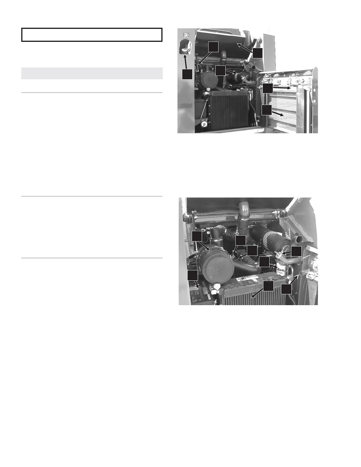
Fig. 10-1: Servicing the Loader
1. Rear Grille Latch and Release Handle
2. Fuel Fill Cap
3. Engine Access Cover
4. Muffler
5. Rear Grille
6. Gas-Charged Spring Cylinder
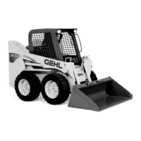
Fig. 10-2: Engine Compartment
1. Oil Cooler
2. Air Cleaner with Air Intake Hose
3. Engine Oil Dipstick
4. Engine Oil Fill Cap
5. Hydraulic Oil Fill Cap
6. Hydraulic Oil Filter
7. Battery
8. Hydraulic Oil Level Indicator
2
1
4
3
5
7
8
2
6
5
4
3
1
6
Service Every 10 Hours or Daily