Outer Element
3. Remove the outer element from the housing.
NEVER remove the inner element unless it is to be
replaced.
4. Clean out the dirt built up in the housing. Leave the
inner element installed during this step to prevent
debris from entering the engine intake manifold.
5. Gehl does not recommend repeated cleaning of the
outer filter. However if it is done, use the following
procedure:
Compressed Air (maximum pressure - 30
PSI):
Move the air nozzle up and down the inside of the
element as you rotate it. DO NOT rap the element
on a hard surface.
Use a trouble light inside the outer element to
inspect for spots, pinholes or ruptures. Replace the
outer element if any damage is noted. The outer
element MUST be replaced if it is oil or soot-laden.
Inner Element
NOTE: Replace the inner element only if it is dirty
or if the outer element has been cleaned or
replaced three times.
6. Before removing the inner element from the
housing, clean out the dirt built up in the housing.
Leave the inner element installed during this step to
prevent debris from entering the engine intake
manifold. Remove the inner element.
Reinstallation
7. Check the inside of the casing for any damage that
may interfere with the elements.
8. Make sure that the filter sealing surfaces are clean.
9. Insert the element(s), making sure that they are
seated properly.
10. Secure the cover to the housing with the three
clamps.
11. Check the tube connections and make sure they are
all engaged and tightened properly.
12. Reset the indicator by pushing in the reset button
located on the end of the indicator.
Clean Oil Cooler Fins
CAUTION
Allow sufficient time for the oil cooler to cool
BEFORE attempting to work around it. Parts
get extremely HOT during operation and can
burn you.
The oil cooler assembly is mounted between the engine
and the hinged rear grille. When operating correctly, air
is blown through the openings between the coils and fins
by the engine fan. During normal operation dust and
debris builds up on the engine side of the oil cooler and
restricts air flow through the fins. To reduce or remove
this restriction, use compressed air or a water hose and
direct the flow through the fins from the rear of the
cooler towards the engine.
Grease Lift Arm, All-Tach /Quick-Tach
Attachment and Cylinder Pivots
Lubricate all lift arm pivots and All-Tach /Quick-Tach
attachment pivots. Lubricate the fittings on both ends of
all four cylinders. Refer to details in the Lubrication
chapter.
PRINTED IN USA 63 907808/CP0300
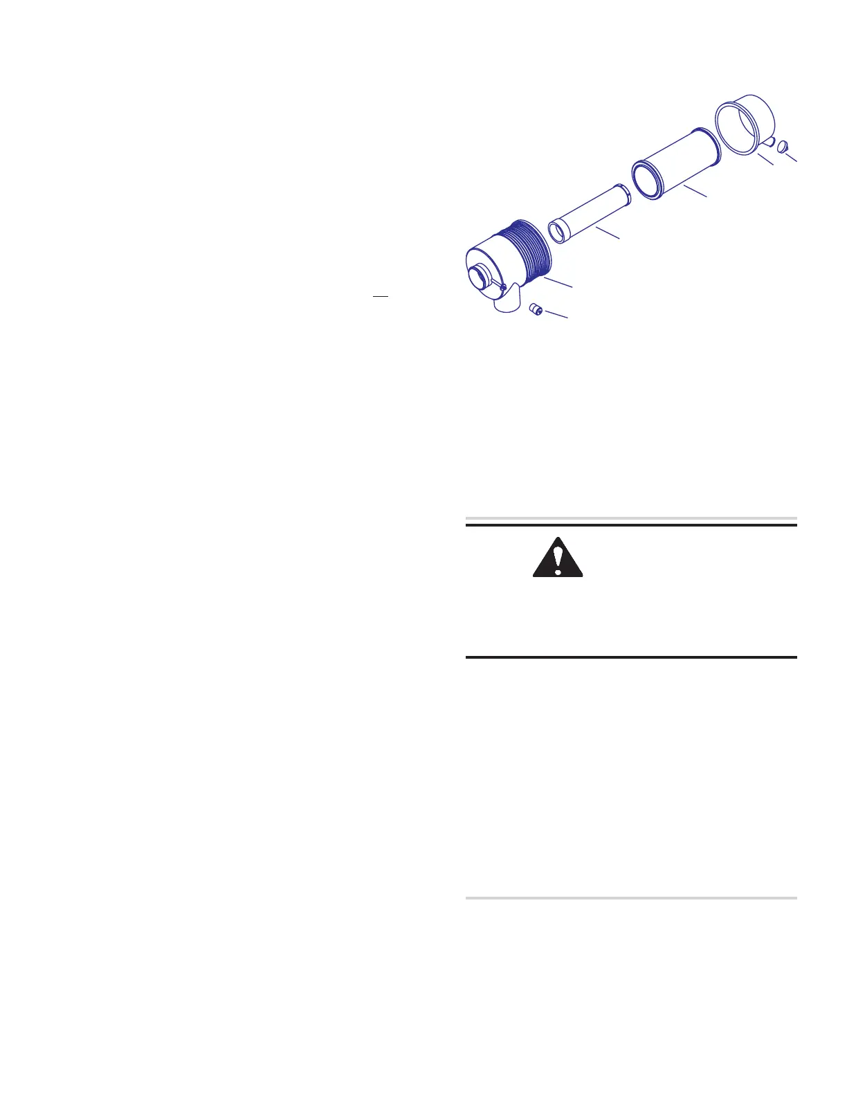
Fig. 10-3: Dual Element Air Cleaner
1. Air Cleaner Restriction Sensor Switch
2. Element Housing & Inlet Assembly
3. Inner Filter Element
4. Outer Filter Element
5. Element Cover
6. Dust Ejector
1
2
3
4
5
6