Auxiliary Hydraulics
Auxiliary hydraulics are used on an attachment that has
a mechanism requiring hydraulic power of its own.
Standard Flow Auxiliary Hydraulics
(Fig. 5-16)
Skid loaders are shipped from the factory with standard
flow auxiliary hydraulics with flat face disconnect
couplers. The couplers are located under the lift arm on
the left hand side.
A second set of hydraulic disconnect couplers can be
added to the front of the lift arm by ordering field
installation kit 807233.
Standard auxiliary hydraulics can be added to an
SL4635 by ordering field installation kit 807239.
T-Bar and Dual Hand controlled loaders: A foot pedal
is used to control the direction of oil flow. A stop is
provided to lock the foot pedal for continuous operation.
Hand & Foot controlled loaders with electric auxiliary
hydraulics: A 3-position momentary switch is located
on the right control handle and a 3-position detent
switch for continuous operation is located on the
instrument panel for operating the auxiliary hydraulics.
Hand & Foot controlled loaders with mechanical
auxiliary hydraulics: The right control handle can be
rotated up and down. It can be locked in the up position
for continuous operation of the auxiliary hydraulics.
High Flow Auxiliary Hydraulics
(Fig. 5-17 & 5-18)
In addition to standard flow auxiliary hydraulic
connections, DX model loaders are shipped from the
factory with reversible high flow auxiliary hydraulics.
These additional quick-disconnect fittings are located
under the right lift arm. They are used for operating high
oil flow hydraulic attachments (cold planer,
snowblower, etc.).
A 3-position control lever is located to the right of the
right control lever. The lever is spring centered with a
detent in the forward position for continuous operation.
A blue light on the instrument panel indicates that the
high flow is engaged.
907808/CP0300 36 PRINTED IN USA
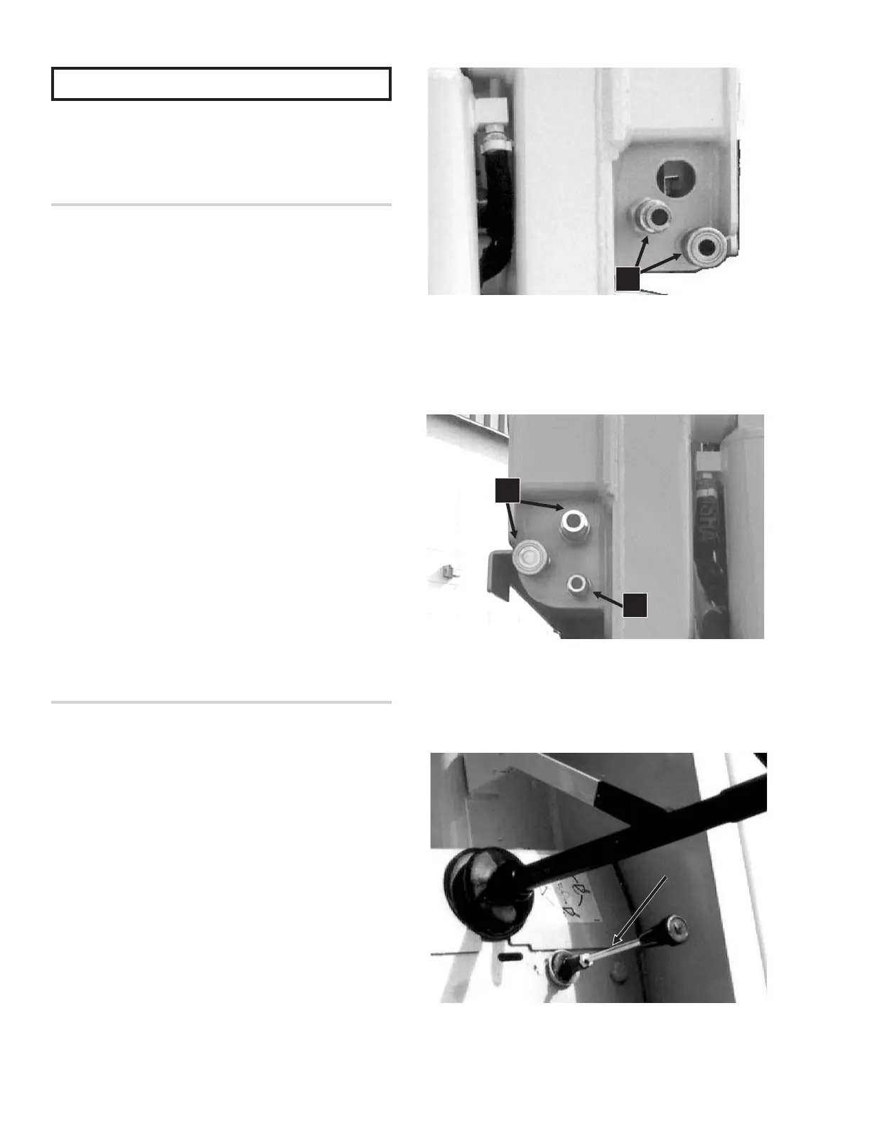
Fig. 5-16: Standard Flow Auxiliary Hydraulics
1. Standard Flow Quick-Disconnects
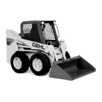
Fig. 5-17: High Flow Auxiliary Hydraulics
1. High Flow Quick-Disconnects
2. Case Drain Line
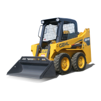
Fig. 5-18: High Flow Control Lever
1
1
2