Cinterion
®
LTE Terminals Hardware Interface Description
3.5 RS-232 Interface
47
ELSxT_HID_v04 2018-09-04
Confidential / Preliminary
Page 28 of 102
3.5 RS-232 Interface
The interface is implemented as a serial asynchronous transmitter and receiver conforming to
ITU-T V.24 Interchange Circuits DCE. It is configured for 8 data bits, no parity and 1 stop bit,
and can be operated at bit rates from 1200bps to 921kbps. Autobauding supports bit rates from
1.2kbps to 230kbps.
For more information see also Section 3.5.1.
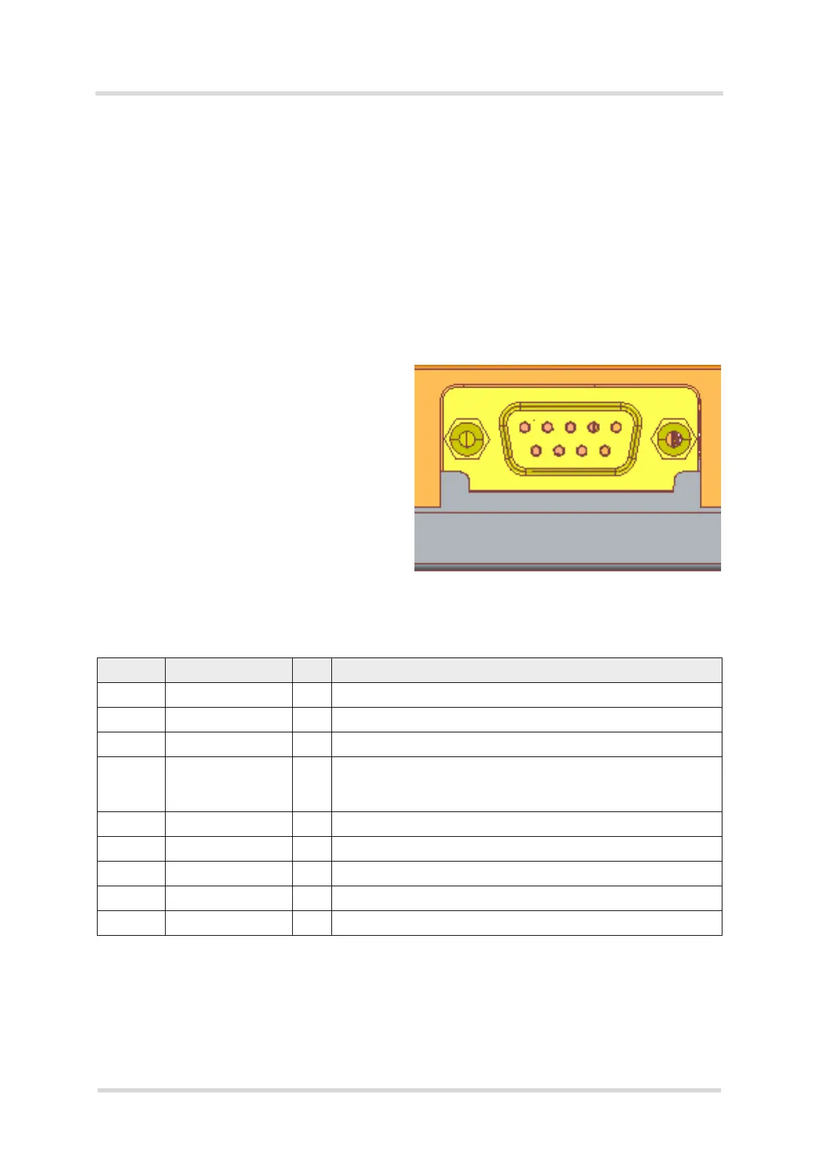
3.5.1 9-Pole D-sub Connector
Via RS-232 interface, the host controller controls the LTE Terminals and transports data.
Figure 7: Pin assignment RS-232 (D-sub 9-pole female)
LTE Terminals are designed for use as a DCE. Based on the conventions for DCE-DTE con-
nections it communicates with the customer application (DTE) using the following signals:
• Port TxD @ application sends data to TXD0 of the LTE Terminals
• Port RxD @ application receives data from RXD0 of the LTE Terminals
Table 13: 9-pole D-sub (female) RS-232
Pin no. Signal name I/O Function
1 DCD0 O Data Carrier Detected
2 RXD0 O Receive Data
3 TXD0 I Transmit Data
4 DTR0 I Data Terminal Ready
Attention: The ignition of LTE Terminals is activated via a rising
edge of high potential (+3 ... +15 V)
5 GND - Ground
6DSR0
1
1. Note that DSR0 may also be available via GPIO connector pin - see Section 3.6.
O Data Set Ready
7 RTS0 I Request To Send
8 CTS0 O Clear To Send
9 RING0 O Ring Indication