Cinterion
®
LTE Terminals Hardware Interface Description
8.4 Qualified Watchdog Configuration
101
ELSxT_HID_v04 2018-09-04
Confidential / Preliminary
Page 88 of 102
8.4.1.3 I
2
C Protocol Overview
In write mode (i.e., slave address “0xD4“), one address byte and one data byte is sent to the
LTE Terminal/Watchdog. The address byte specifies a register to write the data byte to. The
data byte value is only written, if it is valid, i.e., in the specified range. After a write attempt, the
status code of the operation is saved and the read address register (RAR) is automatically set
to the status register address (SR). A subsequent read command from the status register (SR)
will then return the latest status code (see Table 30). Only when the address byte is the RAR,
i.e. another register is selected to be read, the RAR is not automatically set to the SR register.
See Section 8.4.1.4 for sample watchdog configurations via I
2
C.
In read mode, one data byte can be read from the LTE Terminal/Watchdog. Attempts to read
more bytes will result in undefined values being returned by the device. The device will always
return the value that is addressed by the RAR. To read a specific register, a write command
with RAR as the address byte and the register to be read as the data byte has to be issued first.
The next read will then return the value at this address. Note that there are only a few registers
that can be read (see register table - Table 29). When the RAR is written with a non-read ad-
dress, the RAR is set to the SR, and the status code ILLEGAL_ARGUMENT is saved. Note
also that a consecutive read is not valid, as the return value will be ILLEGAL_ARGUMENT, but
the caller cannot determine whether the result is the value at the faulty address or an error sta-
tus code. See Section 8.4.1.4 for sample watchdog configurations via I
2
C.
8.4.1.4 I
2
C Commands
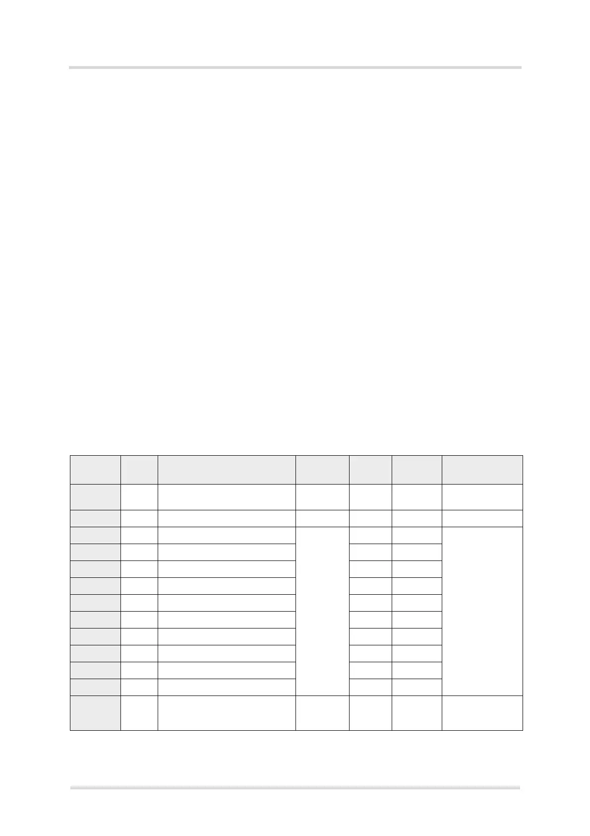
The following table lists the address register for configuration commands via I
2
C interface.
Table 29: Address register for I
2
C commands
Register
address
Read/
Write
Description Name Non-
volatile
Default Value range
0x00 R Status; only address register to
read directly from.
SR - OK See result codes
Table 30
0x09 W RST_I2C Yes 0
0x10 W GPIO6 GPIOxR Yes 0 Level shifter‘s
GPIO direction:
0: Input
1: Output
0x11 W GPIO7 Yes 0
0x12 W GPIO8 Yes 0
0x13 W GPIO11 Yes 0
0x14 W GPIO12 Yes 0
0x15 W GPIO13 Yes 0
0x16 W GPIO22 Yes 0
0x17 W GPIO23 Yes 0
0x18 W GPIO21 Yes 0
0x19 W GPIO20 Yes 0
0x30 R GPIO direction Low Byte:
Read out 8 bits for the GPIOs
[15,14,13,12,11,8,7,6]
GPIOLBR - [0..0xFF]
 Loading...