Cinterion
®
LTE Terminals Hardware Interface Description
3.6 GPIO Interface
47
ELSxT_HID_v04 2018-09-04
Confidential / Preliminary
Page 35 of 102
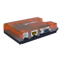
single channel PCM CODEC chip (AK2300), has a fixed terminal block (green connector) in
order to connect easily to the Terminal ELS61T-E2 and a 3.5 mm plug connector for the head-
phone.
The DAI Interface supports following configurations:
• 256 kHz long frame synchronization master mode
• 16 Bit linear
• 8 kHz sample rate
• The most significant bit MSB is transferred first
• Data write at rising edge / data read at falling edge
• Common frame sync signal for transmit and receive
Figure 15: Audio Codec Board
The signal “Call Button” indicates the state of the Call Button on the headphone and should be
connected to GPIO.
3.6.2.3 Manual configuration via AT-Commands
Following steps have to be done:
• Connect the Terminal with the PC via RS-232 Interface.
• Open for instance an HTerm and open Port (115200, 8N1, no flowcontrol).
• enter following AT commands:
• at^scfg="Gpio/mode/DAI","std" // set GPIOs in the module to DAI functionality
• at^sspi= // open I2C connection
• <aD41601> // set GPIO 22 to output (TFSDAI)
• <aD41701> // set GPIO 23 to output (SCLK)
• <aD41800> // set GPIO 21 to input (RXDDAI)
• <aD41901> // set GPIO 20 to output (TXDDAI)
DOUT
DIN
GND
VREF
5V
BCLK
FSC
Call
Button
Head-
phone
3.5 mm
Activity
LED