Cinterion
®
LTE Terminals Hardware Interface Description
3.6 GPIO Interface
47
ELSxT_HID_v04 2018-09-04
Confidential / Preliminary
Page 29 of 102
Hardware handshake using the RTS0 and CTS0 signals and XON/XOFF software flow control
are supported.
In addition, the modem control signals DTR0, DSR0, DCD0 and RING0 are available. The mo-
dem control signal RING0 (Ring Indication) can be used to indicate, to the cellular device ap-
plication, that a call or Unsolicited Result Code (URC) is received. There are different modes
of operation, which can be set with AT commands.
Note: The DTR0 signal will only be polled once per second from the internal firmware of LTE
Terminals.
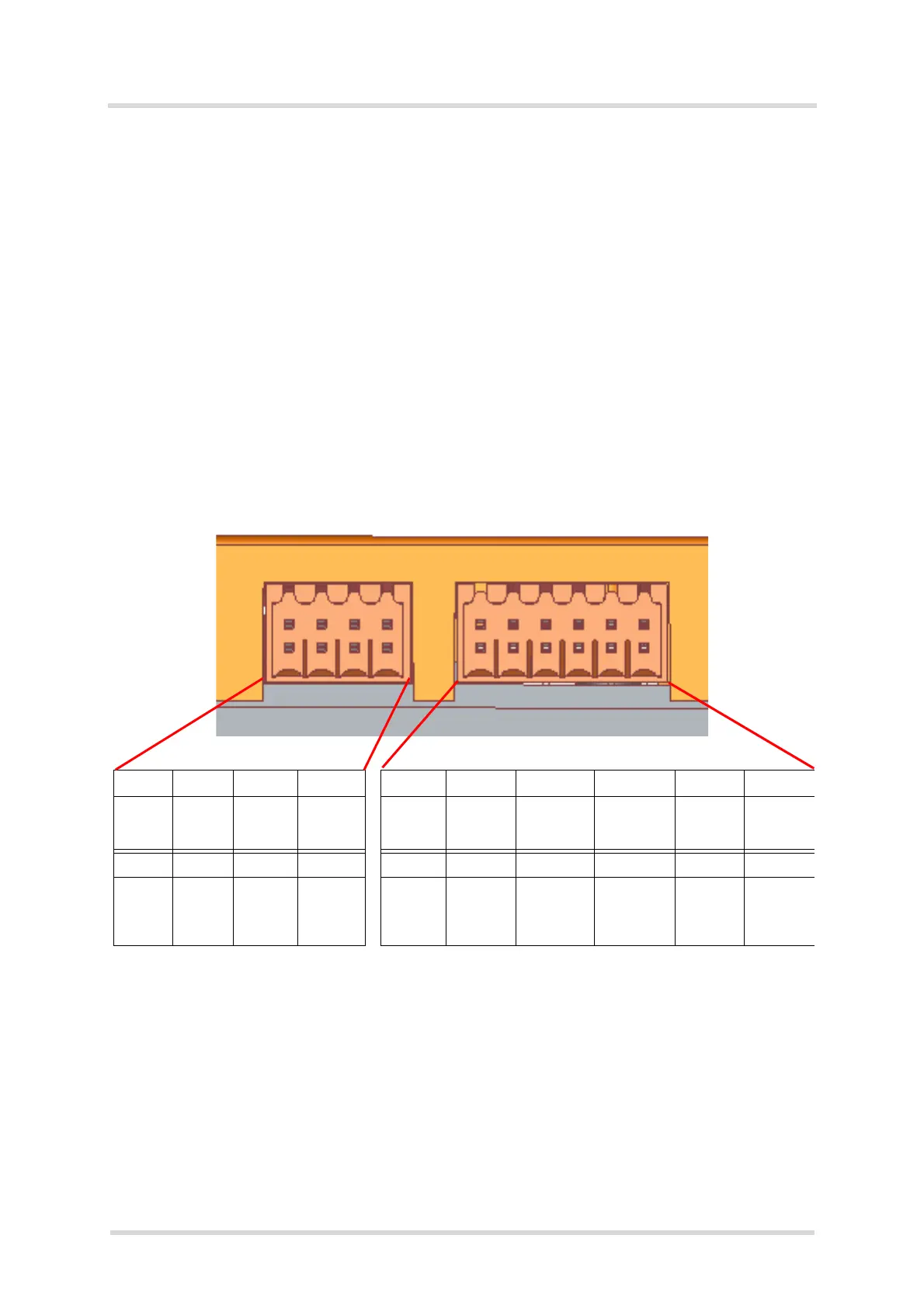
3.6 GPIO Interface
The GPIO connectors (8-pin and 12-pin) provide access to various module signals including a
number of configurable GPIOs. Note that not all of the pins are available for every LTE Terminal
variant. The following figures show the available pins for the LTE Terminal variants and the be-
low Table 14 lists the overall availability of the pins.
Figure 8: ELS61T-US/AUS: GPIO connectors (8-pin and 12-pin)
12 3 4 1 2 3 4 5 6
GPIO6 GPIO7 GPIO8 GPIO11 VCCref GND TXD1/
SPI_MISO
RXD1/
SPI_MOSI
CTS1
(RS232)/
SPI_CS
RTS1
(RS232)
56 7 8 7 8 9 10 11 12
GPIO12 GPIO13 GPIO22 GPIO23 +5Vout DSR0/
ADC1_IN
/SPI_-
CLK
I2CDAT I2CCLK GPIO20 GPIO21
ELS61T-
US/AUS:
n/a: not applicable
 Loading...