Cinterion
®
LTE Terminals Hardware Interface Description
8.4 Qualified Watchdog Configuration
101
ELSxT_HID_v04 2018-09-04
Confidential / Preliminary
Page 90 of 102
Examples
The following two samples show how the watchdog can be configured by means of the watch-
dog‘s I
2
C interface and using the AT^SSPI command over RS-232/ASC0 to transfer the I
2
C
user data. Please refer to [1] for more information on the AT command AT^SSPI and on how
to configure and control the data transfer over the LTE module‘s I
2
C interface.
The above Table 29 specifies the address register that can be used in I
2
C configuration com-
mands.
The first example sets the level shifter‘s GPIO12 direction to “output“. It therefore configures a
write register marked as “W“ in Table 29. For more information on the configuration of GPIO
directions see Section 8.5.
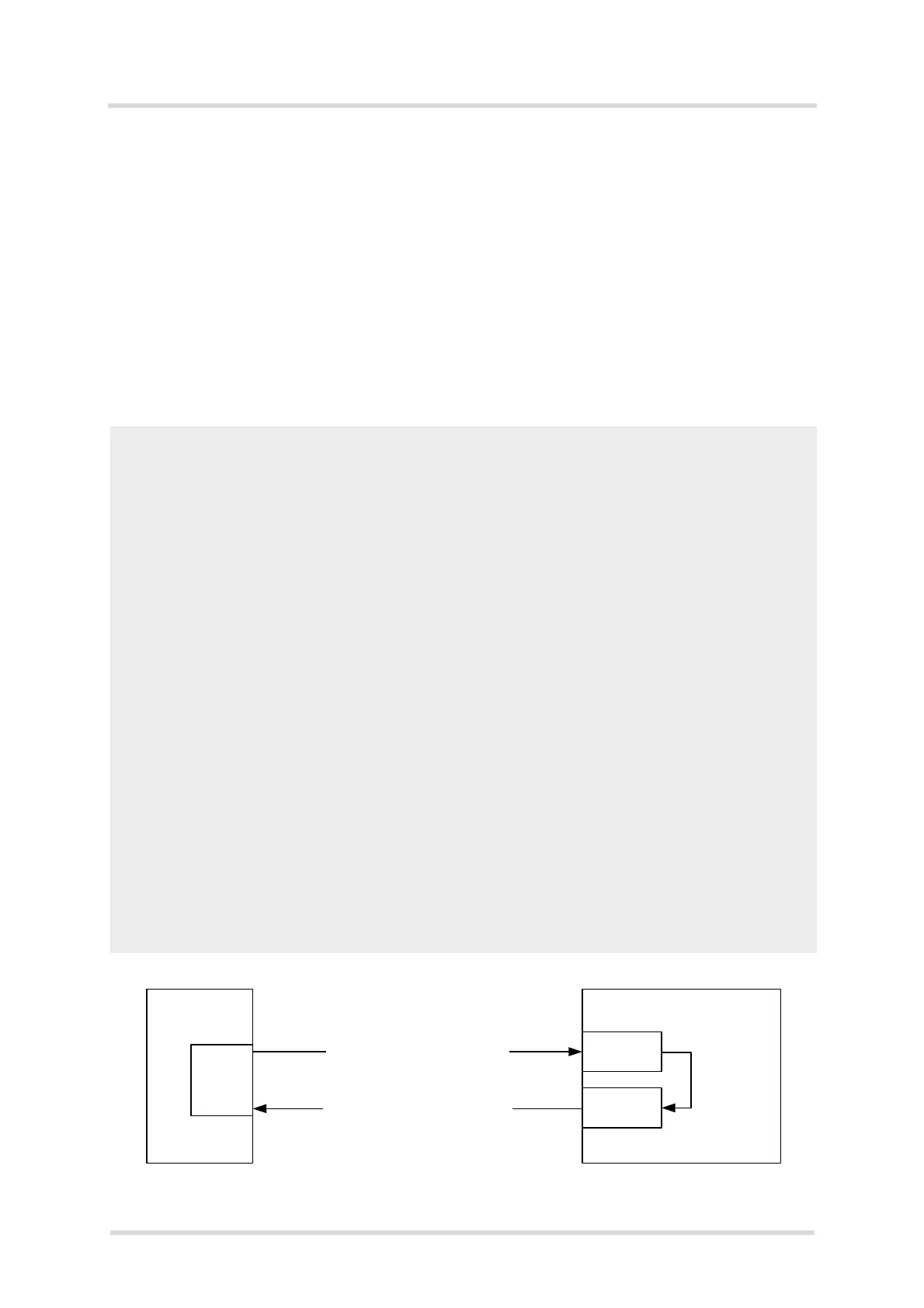
Figure 28: Write data to address register
AT^SSPI=
CONNECT
<aD41401>
{a+}
<bD50001>
{b+00}
#
OK
Open the LTE Terminals I
2
C data connection.
Indicates that the connection is open.
WRITE command enclosed by <>: “a“ is a command ID to better identify and match
acknowledgments, “D4“ indicates the slave address (write mode), “14“ specifies
the address register GPIO12, and “01“ sets the data byte (i.e., line is “output“).
Note: The data byte value is only written if valid, i.e., if in the specified range. After
a WRITE command, the status code of the operation is saved to the status register
(SR) and a subsequent READ command from the status register will then return
the latest status code as listed in Table 30.
Acknowledgement enclosed in curly brackets of a successful data transmission.
READ command enclosed by <>: “b“ is a command ID to better identify and match
acknowledgements, “D5“ indicates the slave address (read mode), “00“ specifies
the address register SR, and “01“ sets the data length to be read. Note: The READ
command can only be called in conjunction with the SR address “00“ and the data
length of one byte “01“.
Acknowledgement enclosed in curly brackets of a successful data transmission,
together with the response code “00“ indicating that the command was successful-
ly executed.
Close data connection.
Connection closed.
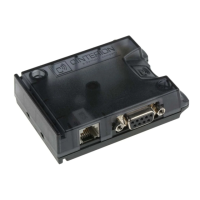
External
Application
Watchdog
Write: Set GPIO12 to “output“
GPIO12:
01
SR:
00
Read from status register (SR)
Command
executed
successfully
E.g.,
RS-232
interface
Access to watchdog via Java Terminal interface and
Java module with its I
2
C lines