Cinterion
®
LTE Terminals Hardware Interface Description
5.2 Mounting the LTE Terminals
65
ELSxT_HID_v04 2018-09-04
Confidential / Preliminary
Page 64 of 102
5.2 Mounting the LTE Terminals
There are a number of ways to mount the LTE Terminals:
• LTE Terminals can be attached to a rail installation or other surface using the two provided
screw holes for screws, e.g., size M3.
• LTE Terminals can be fastened to a rack or holding using the two provided fixtures for cable
straps.
• LTE Terminals can be slid onto a specific DIN rail made according to DIN EN 60715 - C
section, C30 format. A catch at the terminal’s bottom side will have to be removed to slide
multiple terminals onto a single rail.
• Using a BOPLA TSH 35-2 universal DIN rail holder the LTE Terminals can be fitted onto
another special type of DIN rail made according to DIN EN 60715 - Top hat section, 35mm
(e.g., Wago 210-113 steel carrier rail).
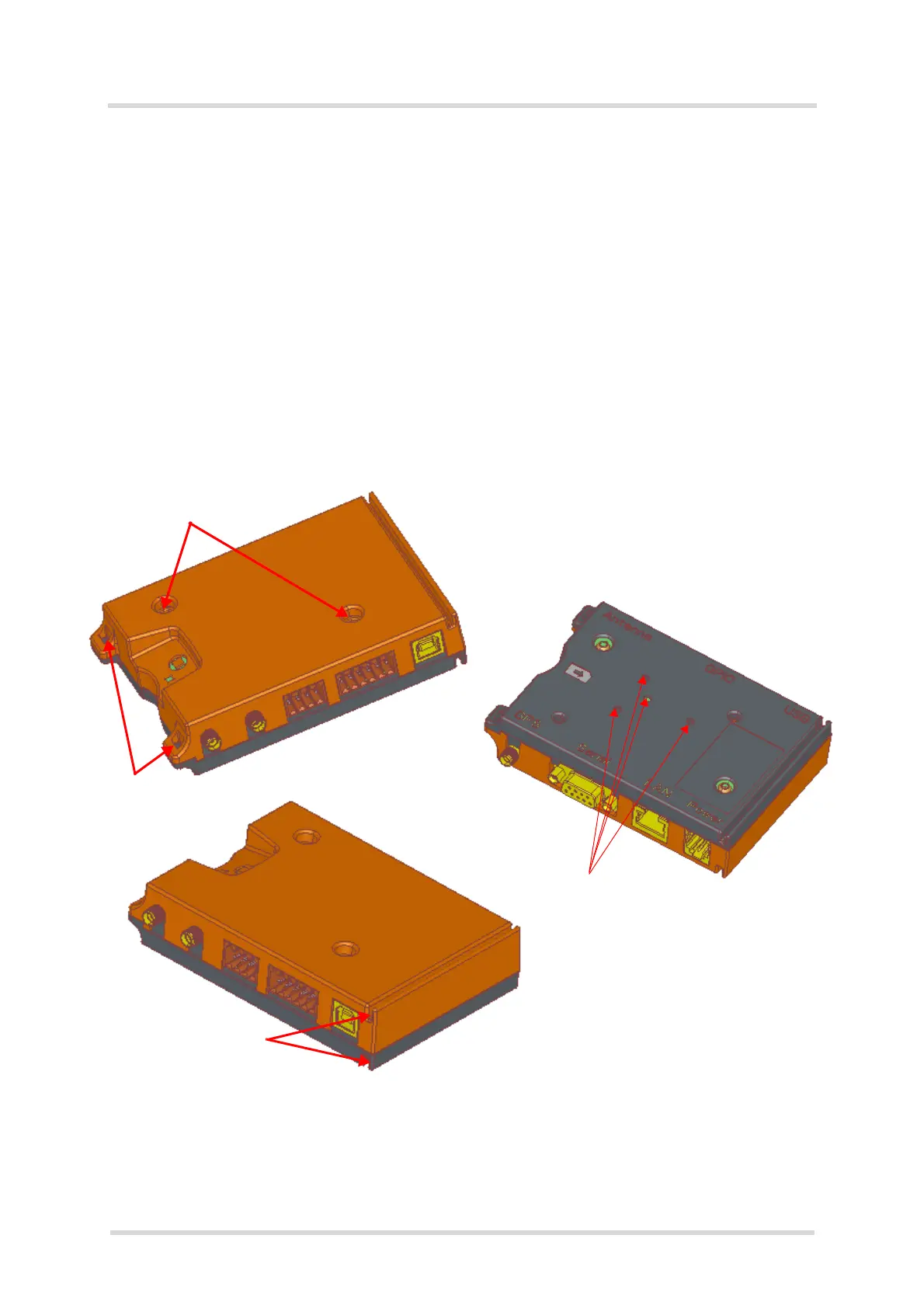
The following figure shows the various possibilities provided to mount the LTE Terminals.
Figure 25: Mounting the LTE Terminals
The various ways to mount the LTE Terminals may be combined where appropriate. It is for
example possible to slide the terminal onto a DIN rail and in addition use cable straps to fasten
it to a holding.
Catch to mount
Screw holes for
Screw holes
Fixtures for
cable straps
DIN rail holder
C-rail (C30)
BOPLA TSH 35-2