Owner’s Manual for Power Zone Gateway on PZ 410 7
Installation and Operation
Section 3: Installation and Operation
Cleaning
Do not use any cleaning solution to clean the Gateway
enclosure or cover. Clean with a damp cloth or sponge.
The Gateway contains electronic circuitry. Use extra cau-
tion not to drip water inside the Gateway. If water or other
liquid enters the Gateway, disconnect power until com-
pletely dry.
Connection Details
Light Emitting Diodes (LEDs)
There are two LEDs at the front on the enclosure:
• Red LED: Represents system power.
– If red LED is on, Gateway is powered.
– If red LED is off, Gateway is not powered.
• Green LED: Represents RS-485 (only) communi-
cation status.
– If green LED is blinking, RS-485 communication
is working properly. The blinking rate will be 0.25
seconds on and 0.25 seconds off (2 Hz).
– If green LED is off, RS-485 communication is not
working properly or RS-485 interface is not con-
nected.
Connecting to the Gateway
The Gateway can be accessed via Ethernet.
Ethernet Connection
1. To connect via Ethernet, the Ethernet IP Address is
required. This information can be accessed via the
Power Zone 410’s Display. See Technical Manual
Power Zone Controller for further details.
NOTE: The IP address and subnet mask on your PC's
Ethernet port must be set to a fixed IP address in the
same subnet range as the IP address of the Gateway.
2. Connect Ethernet cable from the Gateway to the
PC.
3. Open a web browser (Google Chrome™ preferred)
and enter the Ethernet IP address in the top bar of
the browser. After a few minutes, the web browser
should display the Generac app.
(000182a)
WARNING
Equipment damage. Only qualified service personnel may
install, operate, and maintain this equipment. Failure to
follow proper installation requirements could result in death,
serious injury, and equipment or property damage.
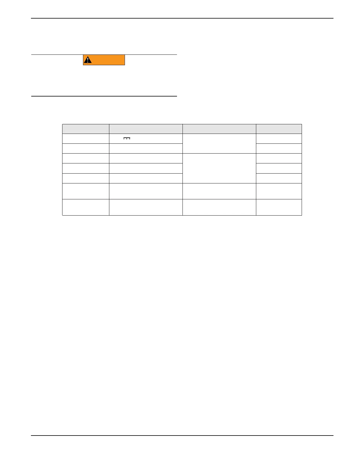
Connector Description Purpose Wire # (Default)
PWR_RS485-5 12 V
Provides power to the
Gateway
15F
PWR_RS485-4 Ground 0C
PWR_RS485-3 RS-485 Ground
This is Modbus Master and is
used to connect to Power
Zone 410 Controller
0B
PWR_RS485-2 RS-485 - 393
PWR_RS485-1 RS-485 + 392
Ethernet RJ-45 Ethernet connector
Used to connect to PC, BMS,
or other external device
–
USB
Universal Serial Bus Type A
connector
Can be used for external add
on USB devices or modules
–

 Loading...


