30 Owner’s Manual for Power Zone Gateway on PZ 410
Installation and Operation
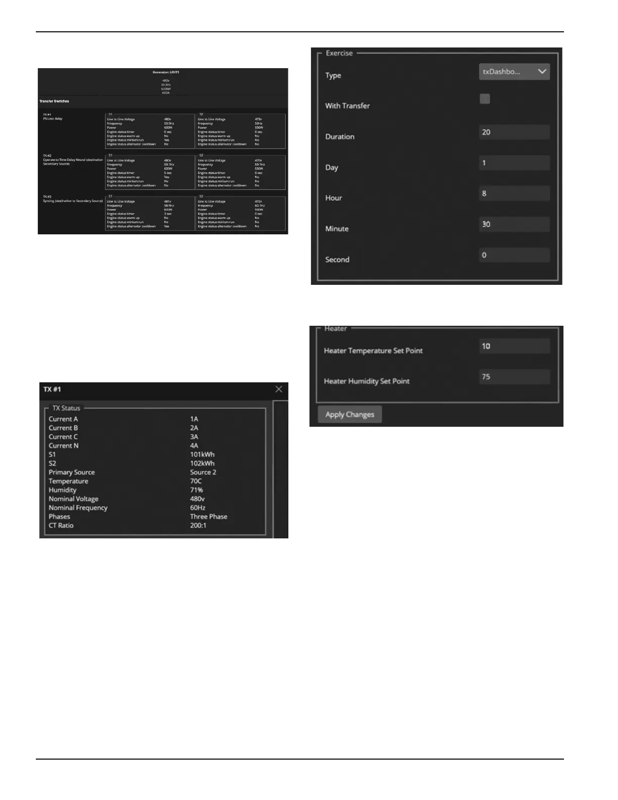
Transfer Switch Dashboard
Figure 3-57. Transfer Switch Dashboard
See Figure 3-57. The Transfer Switch Dashboard
Screen shows the current settings and readings retrieved
from the Transfer Switch Controller. Figure 3-57 shows
three transfer switches connected and details for each
one. For each transfer switch shown, by clicking in a
transfer switches region in the screen, it’s status is shown
along with Exercise and Heater settings that can be
adjusted. See Figure 3-58, Figure 3-59, and Figure 3-
60.
Figure 3-58. Transfer Switch Status
Figure 3-59. Transfer Switch Exercise
Figure 3-60. Transfer Switch Heat and Humidity Settings
015056
015057
015058
015059

 Loading...

