Model S4000T
Quick Start Guide
x
1.3.5 Terminal Block TB3 – Relay Connections
TB3 contains the connections for the Relay Contacts (optional). The function for the
Warn and Alarm Relay connections vary, according to the normal state of the relay.
Use the following as a guide for determining the Normally Open (NO) and the
Normally Closed (NC) contact:
TB3 position Relay Contact (De-Energized) Relay Contact (Energized)
1 Normally Closed Normally Open
2 Common Common
3 Normally Open Normally Closed
Figure 8 Alarm Relay Connections
TB3 position Relay Contact (De-Energized) Relay Contact (Energized)
4 Normally Closed Normally Open
5 Common Common
6 Normally Open Normally Closed
Figure 9 Warn Relay Connections
TB3 position Relay Contact (Energized)
7 Normally Open
8 Common
9 Normally Closed
Figure 10 Fault Relay* Connections
*NOTE - Fault relay is normally energized. Relay will change states after power up.
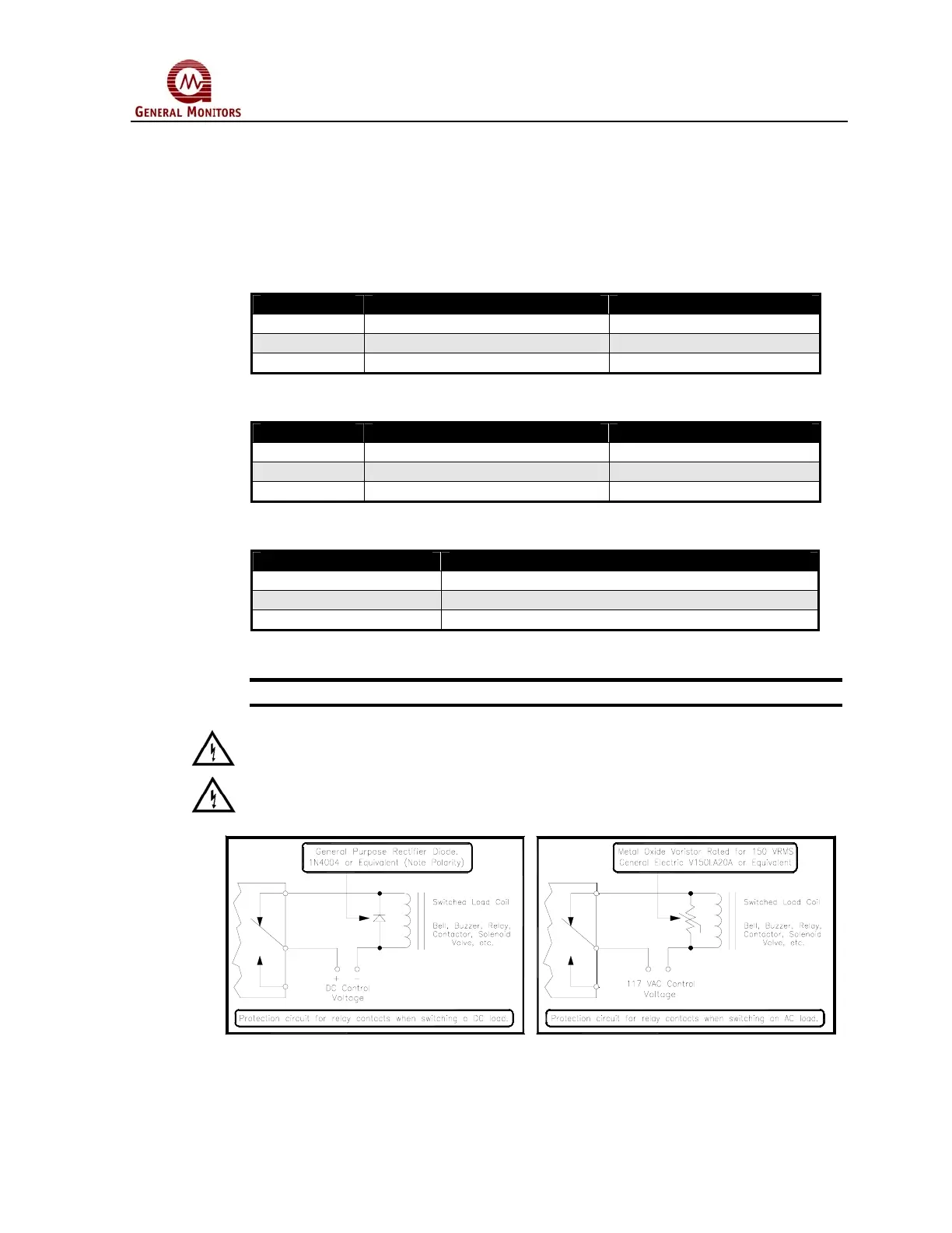
WARNING - Contact with PCB components should be avoided to prevent damage
by static electricity. All wire connections are made to the Terminal Blocks.
WARNING - Relay contacts must be protected against transient and over voltage
conditions (see below).
Figure 11 Relay Protection for DC and AC Loads
 Loading...