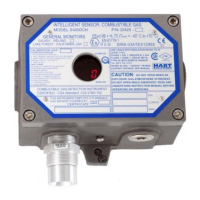
Model S4000T
13
3.6 Maintaining the X/P Integrity
The Model S4000T is rated explosion-proof for the following hazardous locations:
• CSA/FM: Class I, Division 1, Groups B, C, D and Class I, Zone 1, Ex d IIB+H
2
, T6
and
• CENELEC: EEx d IIB, T5 and T6
Some of the factors that influence the explosion-proof integrity of the Model S4000T
housing are:
• Strength of the enclosure material
• Thickness of the enclosure walls
• Flame path between the housing and cover
• Flame path of threaded joints
The acceptable limits for explosion-proof housings that are used in Class I hazardous
locations are defined in CSA Standard C22.2 No.30-M1986, FM 3615 and EN50014.
Anytime the cover of the Model S4000T housing is removed or the cover bolts are
loosened, the flame path between the lid and the housing is effected. If power is to
be left on while removing the cover or loosening the cover bolts on the Model
S4000T, it will be necessary to declassify the area.
When replacing the cover, the gap between the lid and the housing should be less
than .0015 inch (.038 mm). Make sure that the flame path is clear of dirt and debris
before replacing the cover. This can be verified by tightening the cover bolts to a
torque setting of 50 inch-pounds or by using a feeler gauge to ensure the gap
between the cover and the housing is less than .0015 inch (.038 mm).
There are four entry holes, one each on the left and right sides, and two on the
bottom of the Model S4000T housing. These holes are dedicated for the sensor, the
reset switch and conduit. Each hole is tapped for ¾” NPT threads. If a particular entry
hole is not used, it must be plugged during operation in the field. The factory installs
plugs in the unused entry holes, except one. A red plastic cap is placed into the
remaining hole and must be removed before conduit can be attached to the housing.
The Model S4000T will have the following items placed in the three remaining entry
holes, at the factory:
• A sensor, if present (otherwise a red plastic cap)
• A reset switch, if present (otherwise an aluminum housing plug – optional)
• An aluminum housing plug
The sensor, reset switch and aluminum housing plug have seven threads. Each of
these components is screwed into the housing using five to seven turns. If it becomes
necessary to replace the sensor, reset switch and/or the aluminum housing plug, the
user must use five to seven turns to ensure the explosion-proof integrity of the
housing is maintained.
 Loading...