Model S4000T
17
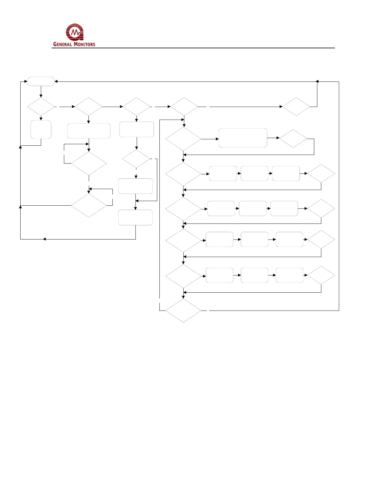
4.4.1 Model S4000T User Menu Structure
Figure 25 User Menu Structure
4.4.2 Sensor Range
The Sensor Range is selectable between 0-20ppm, 0-50ppm, or 0-100ppm
depending on the installed sensor. To adjust the Sensor Range of the Model
S4000T, apply the magnet to the GM Logo on the cover of the unit until “SE” is
displayed, then remove the magnet. This puts the unit into Setup Mode. After a few
seconds “Sr” will be displayed. Apply and remove the magnet to adjust the Sensor
Range. The current Sensor Range will be displayed. To change the sensor range,
apply and remove the magnet repeatedly, until the desired range is displayed. Once
the desired range is displayed, wait 3 seconds and “Fi” will be displayed. Apply and
remove the magnet, to return to the next level of the Setup menu. When “Fi” is
displayed again, apply and remove the magnet to return to normal operation.
Operate
"rSt"
"--" "AC" "SE" "Fi"
Reset
Relays
Enter Calibration
Mode
NN N
Enter Gas Check Mode
pply Gas and
Remove when
com
lete
Gas
Detected?
Gas
Removed?
N
Y
N
"Fi"
Finished?
"Sr"
"Lo"
Warn Relay
"Hi"
larm Relay
"CH1"
Modbus
Channel 1
"CH2"
Modbus
Channel 2
Set Sensor Range
20, 50, 100 ppm
Energized or
De-Energized
Baud Rate
Latching or
Non-Latching
Setpoint
Data Format
ddress
Y
N
Res et
Sensor Life?
Reset Sensor Life
to 100%
Y
N
"Fi"
"Fi"
Energized or
De-Energized
Latching or
Non-Latching
Setpoint
"Fi"
"Fi"
Baud Rate Data Format
ddress
"Fi"
 Loading...