Model S4000T
11
FROM TO
Model
S4000T
Model
DT210
Model
DT220
Model
DT230
Model
TA202A
TB2-1
4-20mA
Output
Rear
CH 1 – 8
4-20mA
Rear
TB1
Pin 8 or 9
Rear
Pin 2 or 5
Analog In
Rear
Pin 26d or
26z
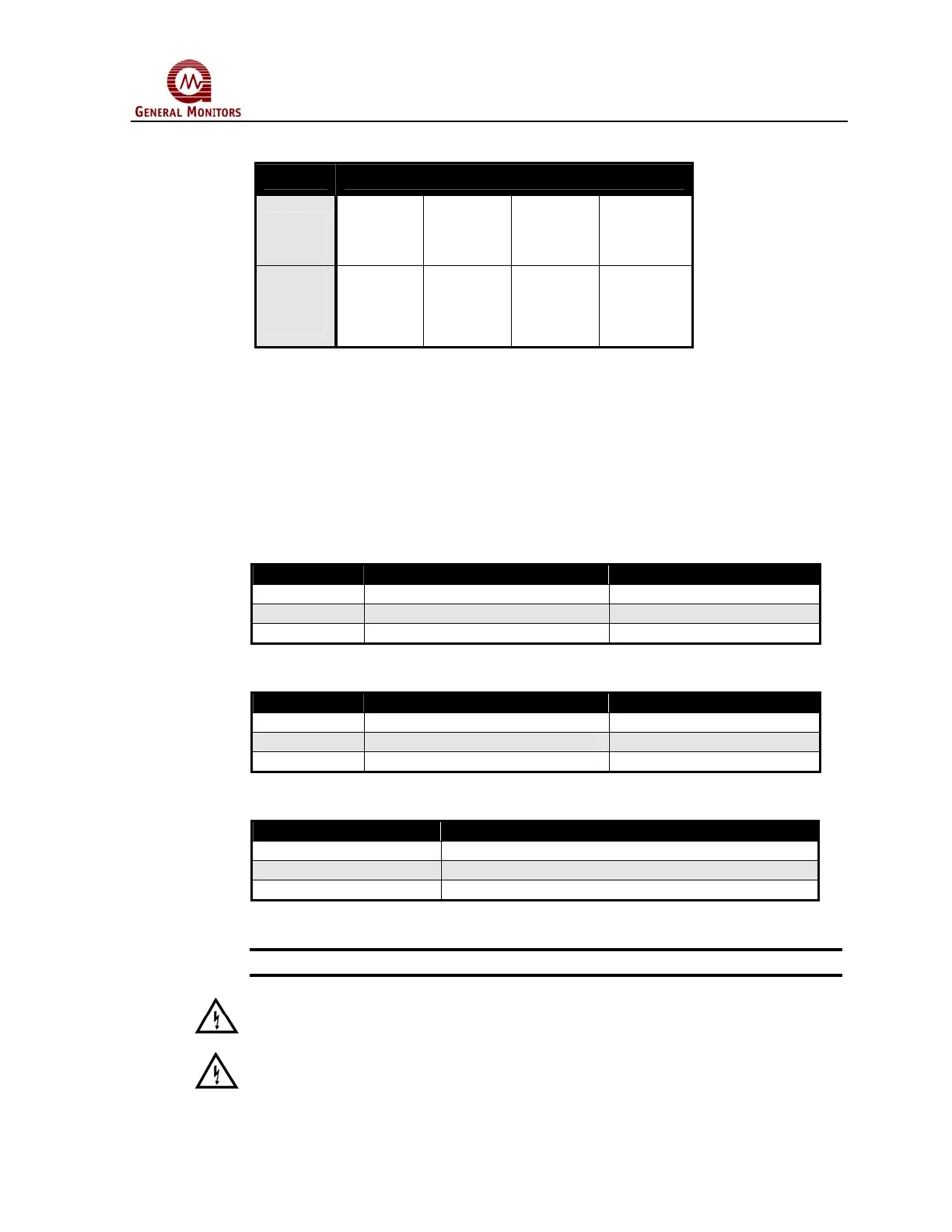
Figure 19 Analog Signal Connections
If a device other than a General Monitors readout/relay display module is being used,
the DC ground, COM, of both systems must be connected together.
3.5.5 Terminal Block TB3 – Relay Connections
TB3 contains the connections for the Relay Contacts (optional). The function for the
Warn and Alarm Relay connections vary, according to the normal state of the relay.
Use the following as a guide for determining the Normally Open (NO) and the
Normally Closed (NC) contact:
TB3 position Relay Contact (De-Energized) Relay Contact (Energized)
1 Normally Closed Normally Open
2 Common Common
3 Normally Open Normally Closed
Figure 20 Alarm Relay Connections
TB3 position Relay Contact (De-Energized) Relay Contact (Energized)
4 Normally Closed Normally Open
5 Common Common
6 Normally Open Normally Closed
Figure 21 Warn Relay Connections
TB3 position Relay Contact (Energized)
7 Normally Open
8 Common
9 Normally Closed
Figure 22 Fault Relay* Connections
*NOTE - Fault relay is normally energized. Relay will change states after power up.
WARNING - Contact with PCB components should be avoided to prevent damage
by static electricity. All wire connections are made to the Terminal Blocks.
WARNING - Relay contacts must be protected against transient and over voltage
conditions (see below).
 Loading...