Model S4000T
33
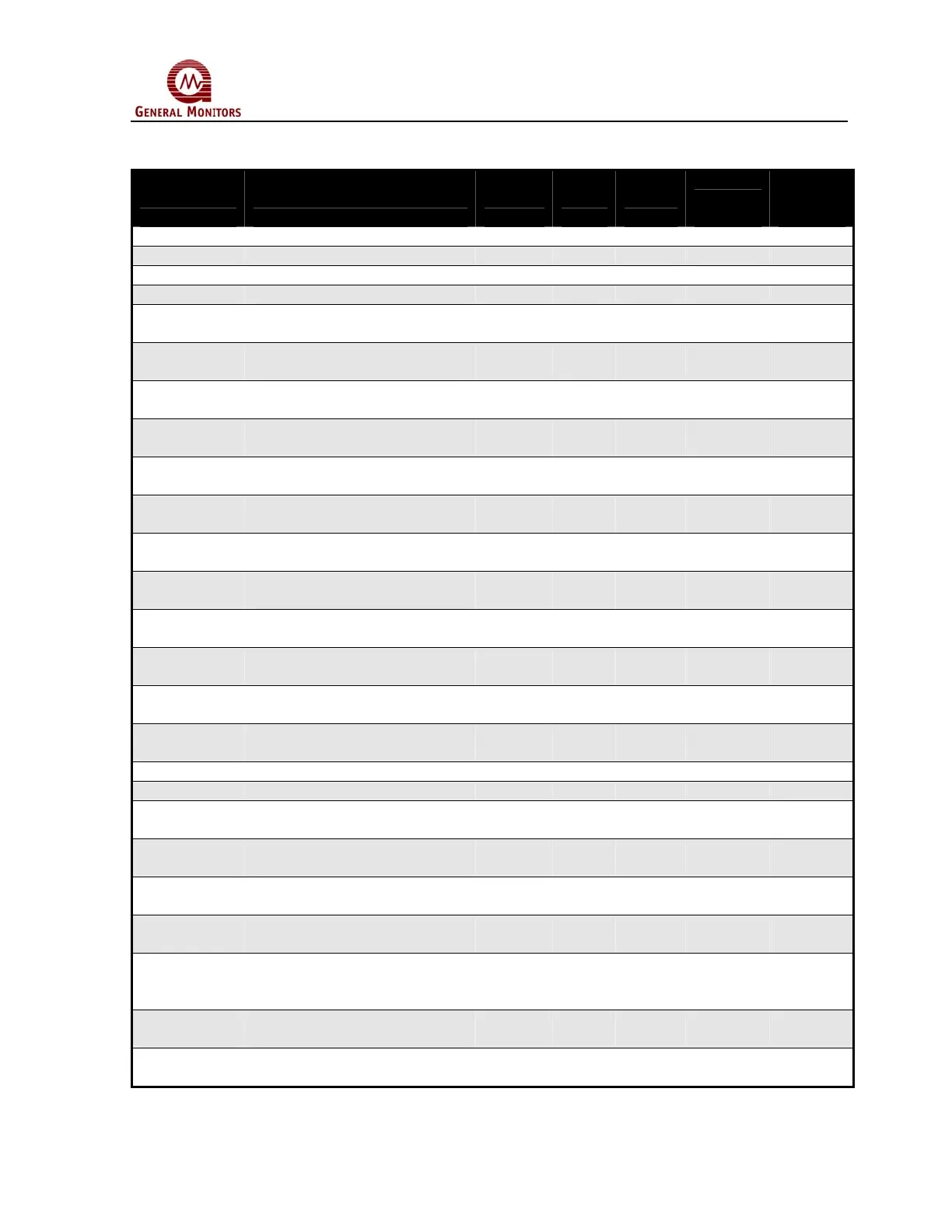
8.7 S4000T Command Register Locations
Parameter Function Type Scale Access
Register
Address
Master
I/O
Address
Analog 0-20mA Current Output Value 16-Bit R 0000 40001
Mode Indicates and Controls Mode Bit R/W 0001 40002
Status/Error Indicates Errors Bit R 0002 40003
Not Used N/A 40004
Unit Type Identifies the S4000T in
Decimal
Value 16-Bit R 0004 40005
Software Rev Indicates the Software
Revision
ASCII 2-
Char
R 0005 40006
Status Block Returns Analog, Mode, Status,
Error, and Sensor Life
Multi 6-
bytes
R 0006 40007
Not Used N/A 40008 –
40013
Alarm
Settings
Read or change settings for
the high alarm
Bit (0-15) R/W 000D 40014
Warn
Settings
Read or change settings for
the low alarm
Bit (0-15) R/W 000E 40015
Com1 Addr. Read or change settings for
the Com1 Address
Value 8-Bit R/W 000F 40016
Com1 Baud Read or change settings for
the Com1 Baud Rate
Bit (0-7) R/W 0010 40017
Com1 Data
Format
Read or change settings for
the Com1 Data Format
Bit (0-7) R/W 0011 40018
Com2 Addr. Read or change settings for
the Com2 Address
Value 8-Bit R/W 0012 40019
Com2 Baud Read or change settings for
the Com2 Baud Rate
Bit (0-7) R/W 0013 40020
Com2 Data
Format
Read or change settings for
the Com2 Data Format
Bit (0-7) R/W 0014 40021
Not Used N/A 40022
Reset Alarms Reset any latched alarms Bit (0) W 0016 40023
Sensor Life Read the Remaining Sensor
Life
Bit (0) R 0017 40024
Sensor Scale
Change the Scale for the H
2
S
sensors on the S4000T
Value 8-Bit R/W 0018 40025
Not Used N/A 40026 -
40032
Total Receive
Errors
Total # of Receive Errors Value 8-Bit R 0020 40033
Bus Activity
Rate %
Bus Activity Rate in % of This
Addressed Node vs. Other
Addressed Nodes
Decimal R 0021 40034
Function
Code Errors
Total # of Function Code
Errors
Value 8-Bit R 0022 40035
Starting Addr.
Errors
Total # of Starting Address
Errors
Value 8-Bit R 0023 40036
Figure 31 Command Register Locations
 Loading...