Model S4000T
8
3.5 Terminal Connections
The terminal blocks (TB) are located inside of the housing and can by accessed by
removing the cover. A label on the inside of the housing cover provides details of all
the terminal connections.
3.5.1 Terminal Block TB1 – Sensor Connections
TB1 contains the four sensor connections, white (W), black (B), red (R) and green
(G). Remove the display board by loosening the two captive screws on the board and
lifting it straight up. Connect the color-coded wires from the sensor to the matching
colored terminals on TB1. The label on the inside of the cover can serve as a guide.
Replace the display board, by pressing it into place, and tightening the two captive
screws.
WARNING - Do not connect +24VDC to TB1. Damage to the electronics or sensor
may result.
3.5.2 Terminal Block TB2 – Power and Signal Connections
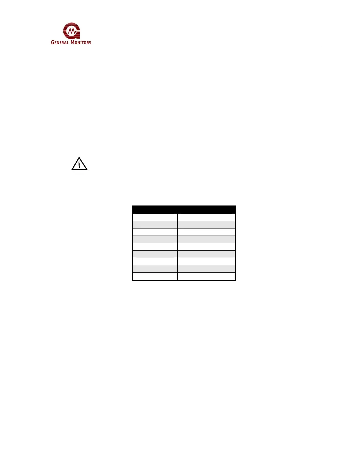
TB2 contains the connections for Power, Relay Reset, Remote Calibration, Modbus
and 0-20mA Output Signal. The terminal connections are as follows:
TB2 position Function
1 0-20mA Output
2 CH1 Modbus -
3 CH1 Modbus +
4 CH2 Modbus -
5 CH2 Modbus +
6 Remote Calibration
7 Relay Reset
8 Ground
9 +24VDC Power
Figure 14 TB2 Power and Signal Connections
 Loading...