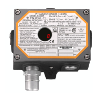
Model S4000T
19
NOTE - The Alarm Relay setpoint cannot be set lower than the Warning Relay
setpoint.
4.4.5 Modbus Channel 1 Settings
To adjust the Modbus Channel 1 settings of the Model S4000T, apply the magnet to
the GM Logo on the cover of the unit until “SE” is displayed, then remove the magnet.
This puts the unit into Setup Mode. After a few seconds “CH1” will be displayed.
Apply and remove the magnet, to change the Modbus Channel 1 settings.
First, the current Baud Rate Modbus Channel 1 is displayed. If it is to be selected,
another baud rate apply and remove the magnet until the desired baud rate is
displayed. The choices are: 19.2 kbaud “19.2”, 9600 baud “96”, 4800 baud “48”, or
2400 baud “24”.
After a few seconds, the current Data Format for Modbus Channel 1 is displayed. If
another data format is to be selected, apply and remove the magnet until the desired
data format is displayed. The choices are: 8-N-1 “8n1”, 8-N-2 “8n2”, 8-E-1 “8E1”, or
8-O-1 “8O1”.
After a few seconds, the current address for Modbus Channel 1 is displayed. Apply
and remove the magnet until the desired address is displayed. Once the desired
address is displayed, wait 3 seconds and “Fi” will be displayed. Apply and remove
the magnet, to return to the next level of the Setup menu. When “Fi” is displayed
again, apply and remove the magnet, to return to normal operation.
Default settings for Channel 1 are: address 1, 19.2 kbaud, 8-N-1.
NOTE - The address can be adjusted from 1 - 247. Channel 1 and Channel 2
addresses may be the same.
4.4.6 Modbus Channel 2 Settings
To adjust the Modbus Channel 2 Settings of the Model S4000T, apply the magnet to
the GM Logo on the cover of the unit until “SE” is displayed, then remove the magnet.
This puts the unit into Setup Mode. After a few seconds “CH2” will be displayed.
Apply and remove the magnet to change the Modbus Channel 2 settings.
First, the current Baud Rate Modbus Channel 2 is displayed. If another baud rate is
to be selected, apply and remove the magnet until the desired baud rate is displayed.
The choices are: 19.2 kbaud “19.2”, 9600 baud “96”, 4800 baud “48”, or 2400 baud
“24”.
After a few seconds, the current Data Format for Modbus Channel 2 is displayed. If
another data format is to be selected, apply and remove the magnet until the desired
data format is displayed. The choices are: 8-N-1 “8n1”, 8-N-2 “8n2”, 8-E-1 “8E1”, or
8-O-1 “8O1”.
After a few seconds, the current address for Modbus Channel 2 is displayed. Apply
and remove the magnet until the desired address is displayed. Once the desired
address is displayed, wait 3 seconds and “Fi” will be displayed. Apply and remove
the magnet to return to the next level of the Setup menu. When “Fi” is displayed
again, apply and remove the magnet to return to normal operation.

 Loading...