Model S4000T
xvii
Table of Figures
Figure 1 S4000T Outline and Mounting Dimensions....................................... vi
Figure 2 Power and Signal Connections .........................................................vii
Figure 3 Terminal Block Operation.................................................................viii
Figure 4 Wire Strip Length..............................................................................viii
Figure 5 Ground or Common Connections...................................................... ix
Figure 6 Power Connections ........................................................................... ix
Figure 7 Analog Signal Connections ............................................................... ix
Figure 8 Alarm Relay Connections................................................................... x
Figure 9 Warn Relay Connections.................................................................... x
Figure 10 Fault Relay* Connections................................................................... x
Figure 11 Relay Protection for DC and AC Loads.............................................. x
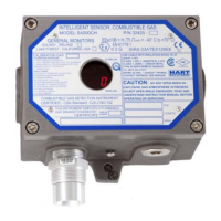
Figure 12 Model S4000T Intelligent Sensor ....................................................... 1
Figure 13 S4000T Outline and Mounting Dimensions........................................ 6
Figure 14 TB2 Power and Signal Connections................................................... 8
Figure 15 Terminal Block Operation................................................................... 6
Figure 16 Wire Strip Length................................................................................ 9
Figure 17 Ground or Common Connections..................................................... 10
Figure 18 Power Connections .......................................................................... 10
Figure 19 Analog Signal Connections .............................................................. 11
Figure 20 Alarm Relay Connections................................................................. 11
Figure 21 Warn Relay Connections.................................................................. 11
Figure 22 Fault Relay* Connections................................................................. 11
Figure 23 Relay Protection for DC and AC Loads............................................ 12
Figure 24 Relay Reset ...................................................................................... 16
Figure 25 User Menu Structure ........................................................................ 17
Figure 26 Gas Check........................................................................................ 20
Figure 27 Automatic Calibration Mode ............................................................. 21
Figure 28 Calibration in Progress Mode ...........................................................21
Figure 29 Calibration Complete Mode.............................................................. 22
Figure 30 Data Format...................................................................................... 29
Figure 31 Command Register Locations ..........................................................33
Figure 31 Command Register Locations, Cont. ............................................... 34
Figure 32 Com1 Baud Rate.............................................................................. 37
Figure 33 Com1 Data Format........................................................................... 37
Figure 34 Com2 Baud Rate.............................................................................. 37
Figure 35 Com2 Data Format........................................................................... 38
Figure 36 Sensor Scale .................................................................................... 38
Figure 37 24VDC Cable Lengths...................................................................... 42
Figure 38 Analog Output Cable Lengths .......................................................... 42
Figure 39 Sensor Cable Lengths...................................................................... 43
 Loading...