30
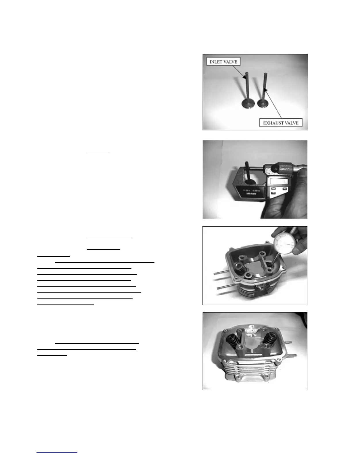
Inspect each valve for turning, burning, scratches
or abnormal stems wear.
Check the valve movement in the guide.
Measure and record each valve stem O.D.
SERVICE LIMITS: 4.90 mm
Measure and record the valve guide I.D.
SERVICE LIMITS: IN / EX 5.30 mm
Calculate the stem-to-guide clearance.
SERVICE LIMITS: IN 0.08 mm
EX 0.10 mm
NOTE: If the stem-to-guide clearance exceeds
the service limits, determine if a new
guide with standard dimensions would
bring the clearance within tolerance.
If so, replace guides as necessary and
ream to fit. If the valve guide is replaced,
the valve guide is replaced; the valve
seat must be refaced.
CYLINDER HEAD ASSEMBLY
Lubricate each valve stem with oil.
Insert the valves into guides.
Install the valve springs, retainers and the cotters.
NOTE: To prevent loss of tension, don’t
compress the valve springs more than
necessary.