A. External
Start/Stop-
Forward/Reverse
Connection –
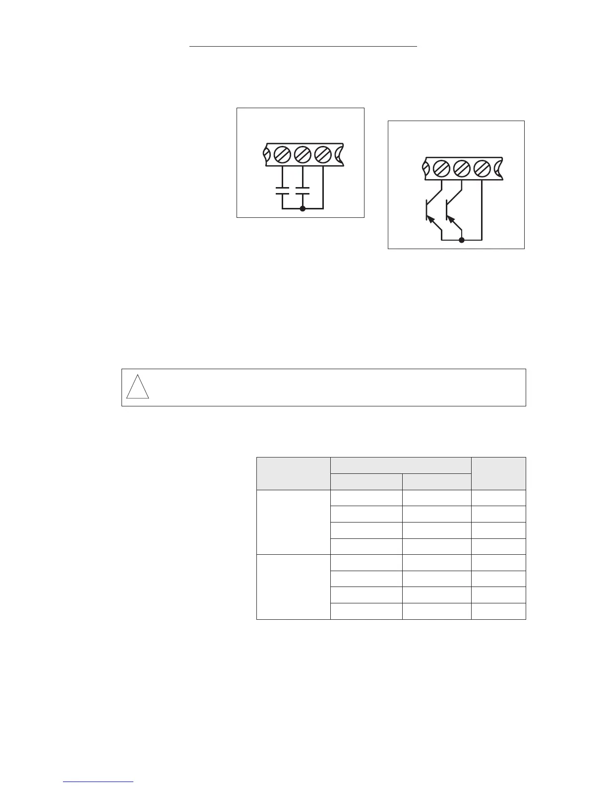
External control of
Start/Stop and
Forward/Reverse
is achieved by
wiring contacts to
Terminals 3, 4, and
5, as shown in
Figure 5A. To program the drive for external
Start/Stop, set F10 [Start/Stop Control] to “001”
[External Contacts], as described in Section IX, on page 42.
The drive is factory programmed to operate Forward/Stop using Terminal 3 and
Reverse/Stop using Terminal 4. To program the drive to operate Run/Stop using
Terminal 3 and Forward/Reverse using Terminal 4, set F03 to “001” [Run/Stop-
Forward/Reverse]. The settings for external Start/Stop control using F03
[External Forward-Stop-Reverse Control] are shown in Table 6.
Note: Open collec-
tors may be used in
lieu of contacts. See
Figure 5B.
B. External Frequency
Control – Terminals
8, 9, and 10 can be
wired in a variety of
ways to control the
output frequency of
the drive, as shown in
Figures 7, 8 and 9,
on pages 21 and 22.
See Table 7 on page 21. F11 [Frequency Control Method] is used to program
the drive to control motor frequency with an external signal instead of the key-
pad, as described in Section IX, on page 42. F11 is factory set to “000”
[Keypad]. SW1 is used to set the drive for voltage or current input signal, as
described in Section V-B-1, on page 21. SW1 is factory set to the “V” position
(Keypad, Potentiometer, 0 - 10 Volts DC).
FIGURE 5A – EXTERNAL
START/STOP-FORWARD/
REVERSE CONNECTIONS
20
Sec. V – Term. Block TM2 Wiring Inst. (Cont.)
WARNING! The Stop contact is never to be used as a Safety
Disconnect since it is not fail-safe. Use only the AC line for this purpose.