to Terminal 9, and the low side to Terminal 10, as shown in Figure 7, on page
21. Set F11 [Frequency Control Method] to “001” [Potentiometer] and be sure
SW1 is set to the “V” position (factory setting). See Section IX, on page 42.
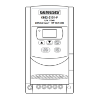
3. Voltage Following
Connection – A 0 - 10
Volt DC analog signal
input can be connect-
ed to Terminal Block
TM2 to control motor
speed. Connect the
signal voltage (+) to
Terminal 9 and the
common (-) to Terminal
10, as shown in Figure 8. Set F11 [Frequency Control Method] to “001”
[0 - 10 V] and be sure SW1 is set to the “V” position (factory setting).
Note: F11 [Frequency Control Method] is factory set to “000” [Keypad].
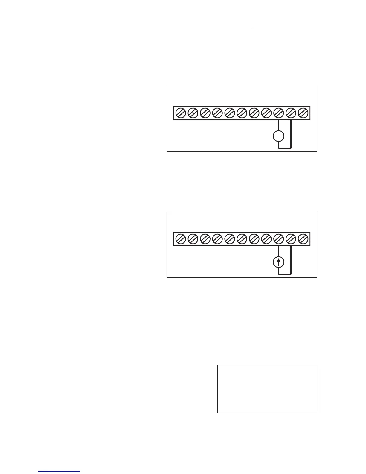
4. Current Following
Connection – A 0 - 20
mA DC or 4 - 20 mA
DC analog signal input
can be connected to
Terminal Block TB2 to
control motor speed.
Connect the signal
current (+) to Terminal
9 and the common (-)
to Terminal 10, as shown in Figure 9. Set SW1 to the “I” position.
a. For 4 - 20 mA DC analog signal input, set F11 [Frequency Control
Method] to “001”.
b. For 0 - 20 mA DC analog signal input, set F11[Frequency Control
Method] to “002”.
5. Multifunction Input Terminals 6 and 7
Connection – The Multifunction Input
Terminals are factory programmed for
Preset Speed #1 (Terminal “6” SP1) and
Reset (Terminal “7” RST). Each terminal
can be programmed for six functions
using Function Numbers F19 for
Terminal “6” and F20 for Terminal “7”.
See Table 8, Figures 10A, 10B, and Table 9 on page 23.
001 Jog
002 Preset Speed #1
003 Rapid Stop
004 Coast-to-Stop
005 Reset
006 Preset Speed #2
FIGURE 8 – VOLTAGE FOLLOWING CONNECTION