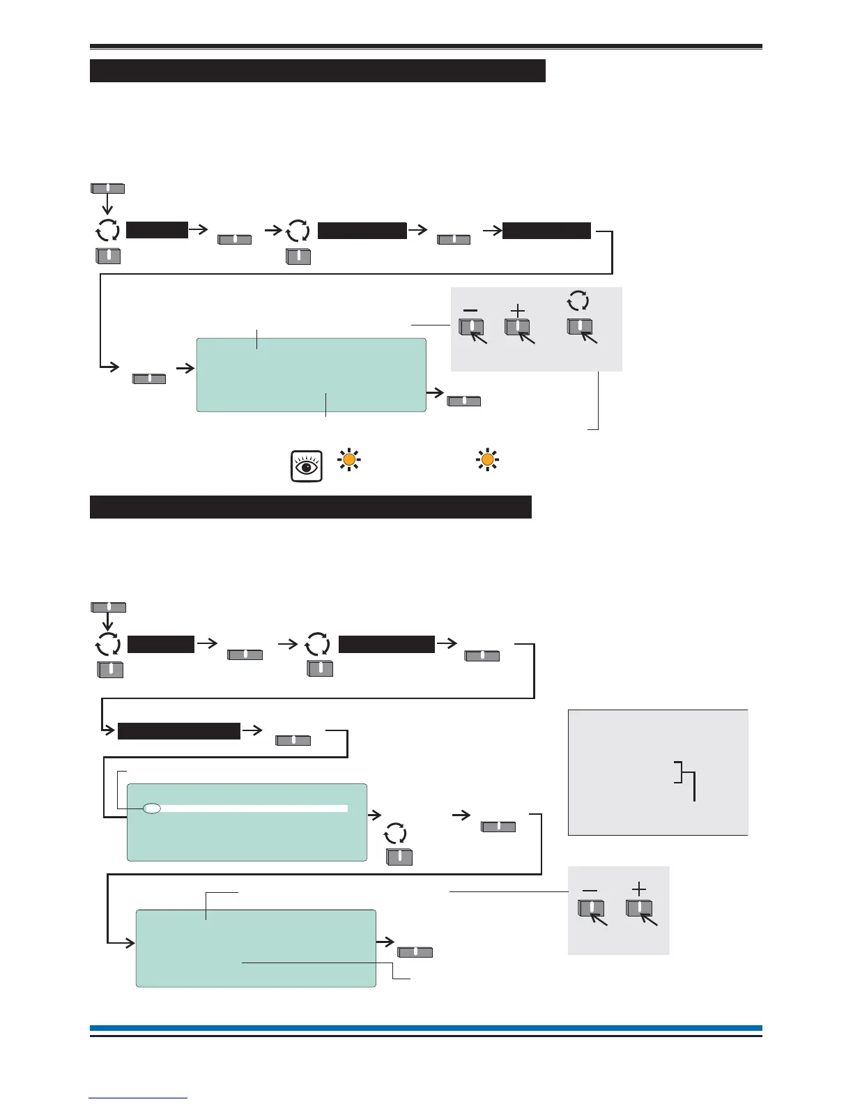
How to view or enable/disable an alarm Sector
The 'Sector' form displays the label given to a sector, its activation control and current status. You can also use
this form to manually disable or enable a sector. A disabled sector will not activate its alarm devices in the
event of a fire and the disablement light(s) will be lit. To view the 'Sector' form you will need to be in the
Customer Mode at Access level 2, see page 9.
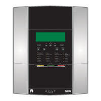
How to view the Loop map and Device details
The 'Loop map' form lists all the devices connected to the loop circuit. You can select a device from the map
and view the 'Device details', which gives information on device label, type, status and assignment. To view
'Loop map' and 'Device details' you will need to be in the Customer Mode at Access level 2, see page 9.
22
Operating instructions
Select from a range of sectors-1to16
Activation Control : EVACUATE
Status Control: [ENABLED ]
Current State: IDLE
Save Quit
10:15 Tue 12/01/10
Sector: [ 1]
Label : Sector Label
Save
Menu
Select
Alarms >
Select
User
Sectors
Select sector status:
Sector ‘ENABLED’ (factory default setting) or Sector ‘DISABLED’,
the latter will give the following indications:
Select
To scroll range
To mo v e t o
next setting
Disablement
[amber LED]
Sounder
Disablement
[amber LED]
DEVICE
Select
10:15 Mon 11/01/10
Device : [ 1]
Label : Device Label
Type : O H Sensor Sounder Strobe
Status : ENABLED
Assigned to Zone 1
Save Quit
2
Select from a range of devices-1to127
Save
10:15 Mon 11/01/10
Loop Map
1+ Device 1
2 Device 2
3 Device 3
4 Device 4
Select Quit
9
9
9
9
Menu
Select
Loop >
SelectSelect
User
Devices
Select
To scroll range
The + indicates the device is SAFE addressed
Device details form
‘Loop map’ form showing devices
connected to the loop circuit.
Loop Map
1+ Device 1
|
20 Device 20
Device 21
Device 22
23 Device 24
9
9
9
9
9
The Devices 21 and 22 are indented,
which implies they are on the spur
circuit off Device 20.
Certain devices will not be assigned to a zone, this
line may or may not be displayed.