28142 Rev 15 PROCESS DESCRIPTION
Gentherm Global Power Technologies Page 13
Fuel System
Components making up the fuel system control the input of fuel to the burner. The primary
control is a pressure regulator that controls the fuel pressure supplied to a metering orifice.
The pressure regulator includes a sediment bowl with a manual drain cock and a fuel filter to
remove fuel impurities. The fuel filter has a resin-impregnated cellulose element which
prevents solid particles from damaging the regulator and downstream parts.
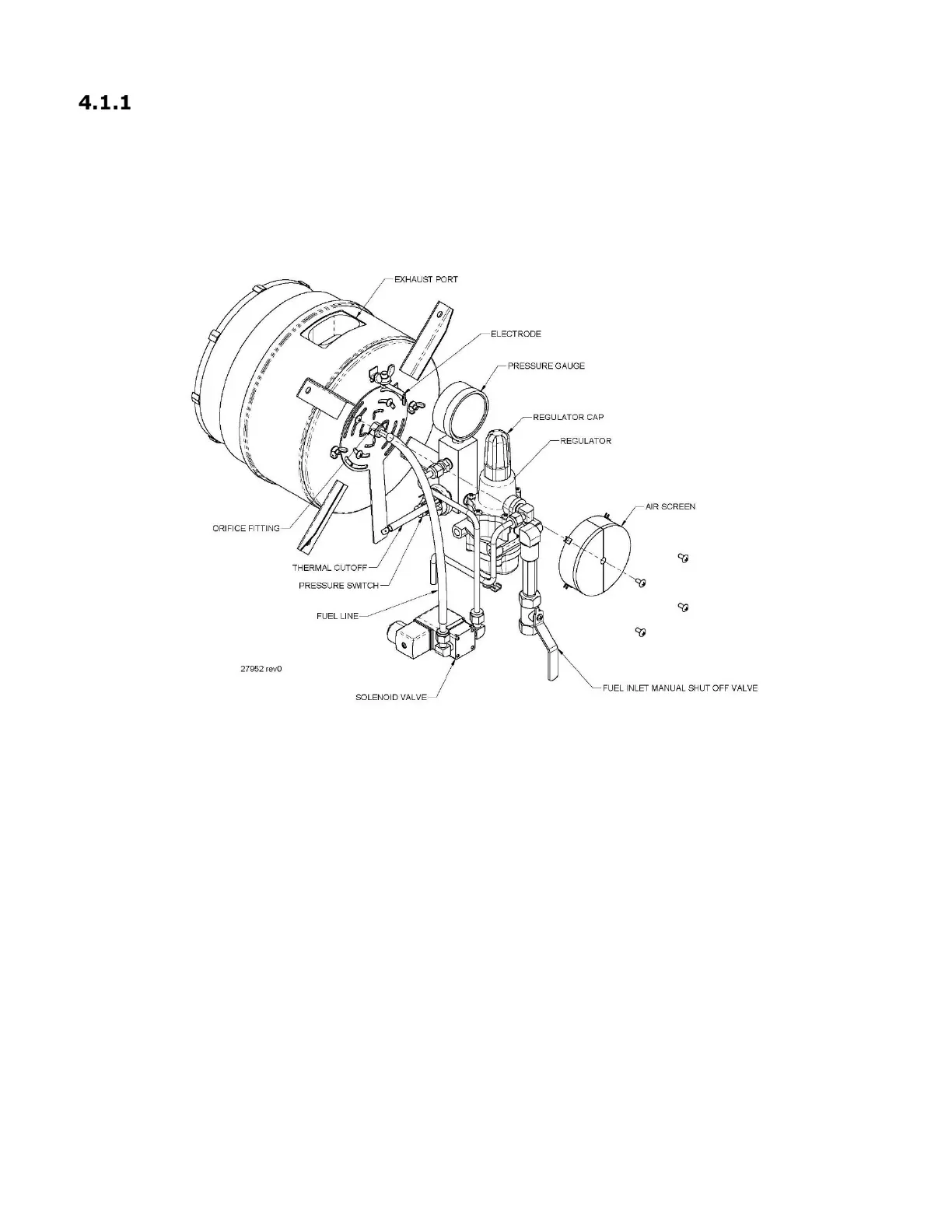
Figure 3 – 5220 Fuel System General Assembly
The outlet of the pressure regulator leads to a manifold. On the manifold there is a pressure
gauge to monitor the fuel pressure and a pressure switch for the SI module. Fuel flows
through the manifold to the fuel line which connects to an orifice mounted on the front of the
burner. The orifice contains a jewel with a precisely sized hole to meter the fuel flow into the
burner. A solenoid valve (SOV) is located beneath the cabinet and plumbed between the
manifold and fuel line, allowing the SI module to control the burner
The solenoid valve is controlled by the Spark Ignition (SI) module. The SI module opens the
solenoid valve when the fuel pressure switch is closed (fuel pressure is present) and closes
the solenoid valve when fuel pressure switch is open (no fuel pressure), or if the SI module
does not sense a flame in the burner. The main parts of fuel system are shown in Figure 3.
 Loading...