28142 Rev 15 TROUBLESHOOTING
Gentherm Global Power Technologies Page 68
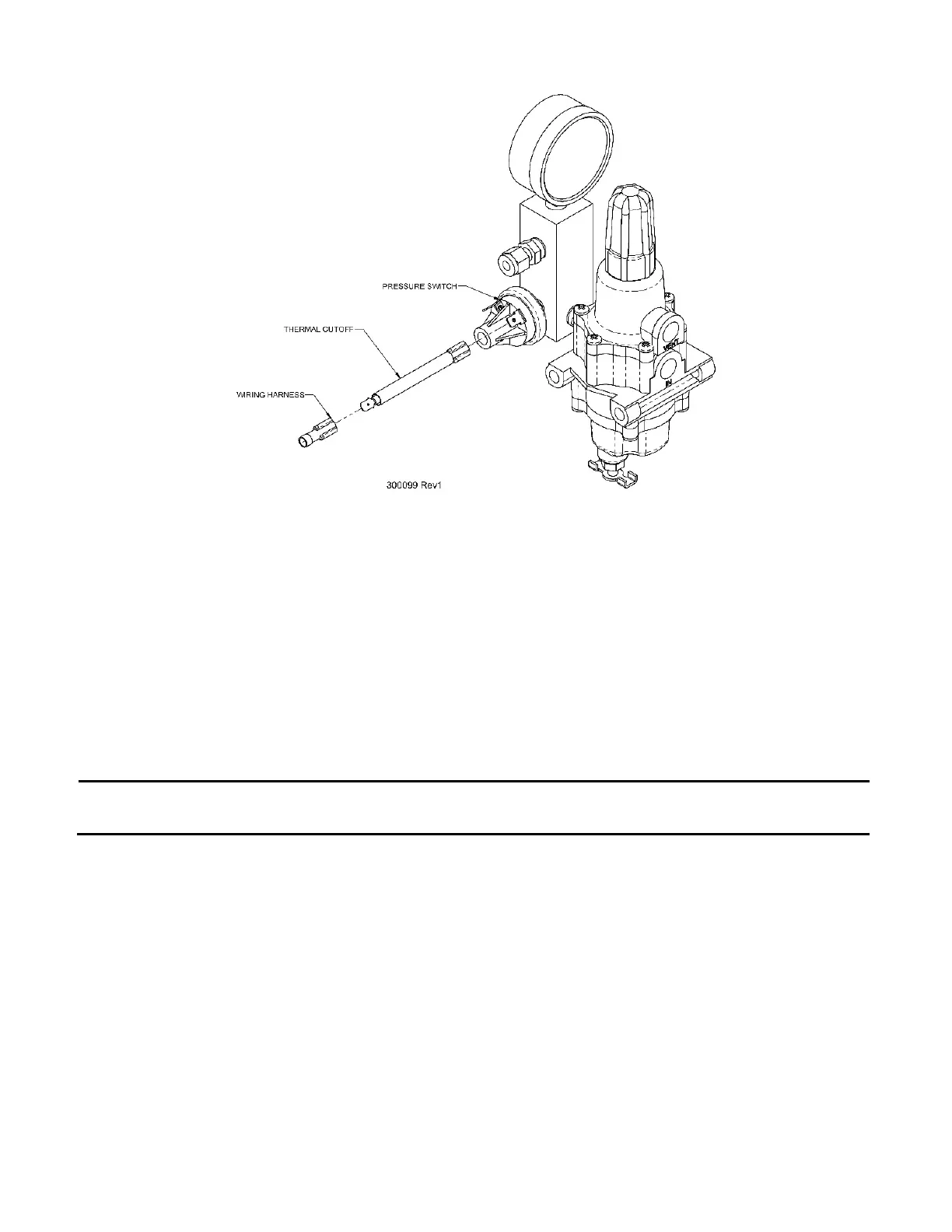
Figure 34 – Thermal Cutoff Installation Diagram
To install a TCO, proceed according to the following steps:
1. Disconnect one of the wires from the pressure switch. Polarity does not matter in the
pressure-sensing circuit, so whichever wire is more easily reached will suffice.
a) For 5220 Remote-Start TEGs equipped with two pressure switches, use the switch
connected with ORANGE wires.
2. Connect the TCO to the vacant terminal on the pressure switch.
3. Connect the free wire to the other end of the TCO.
NOTE:
On Remote-Start TEGs equipped with two pressure switches, the TCO should
be attached to the pressure switch wired with ORANGE wires only.
If the TCO is discovered to be open, simply replacing the TCO may not be enough to solve
the problem. The thermal fuse is set to open if temperatures in the TEG cabinet exceed safe
limits. If the fuse is open, it indicates that it has seen excessive temperature. If possible, the
cause of this excessive temperature should be determined and remedied. After replacing the
open TCO with a new one, check the following items:
• Check that the TEG is equipped with a wind scoop. If not, contact GPT to obtain one.
• Check the fuel system for leaks using a commercial leak detector fluid. Tighten any
leaking connections or replace components as necessary.
• Ensure the fuel gas supplied to the TEG is dry and completely free of liquids.
• Ensure that the TEG is tuned correctly and is making proper power for the ambient
conditions.