28142 Rev 15 PROCESS DESCRIPTION
Gentherm Global Power Technologies Page 16
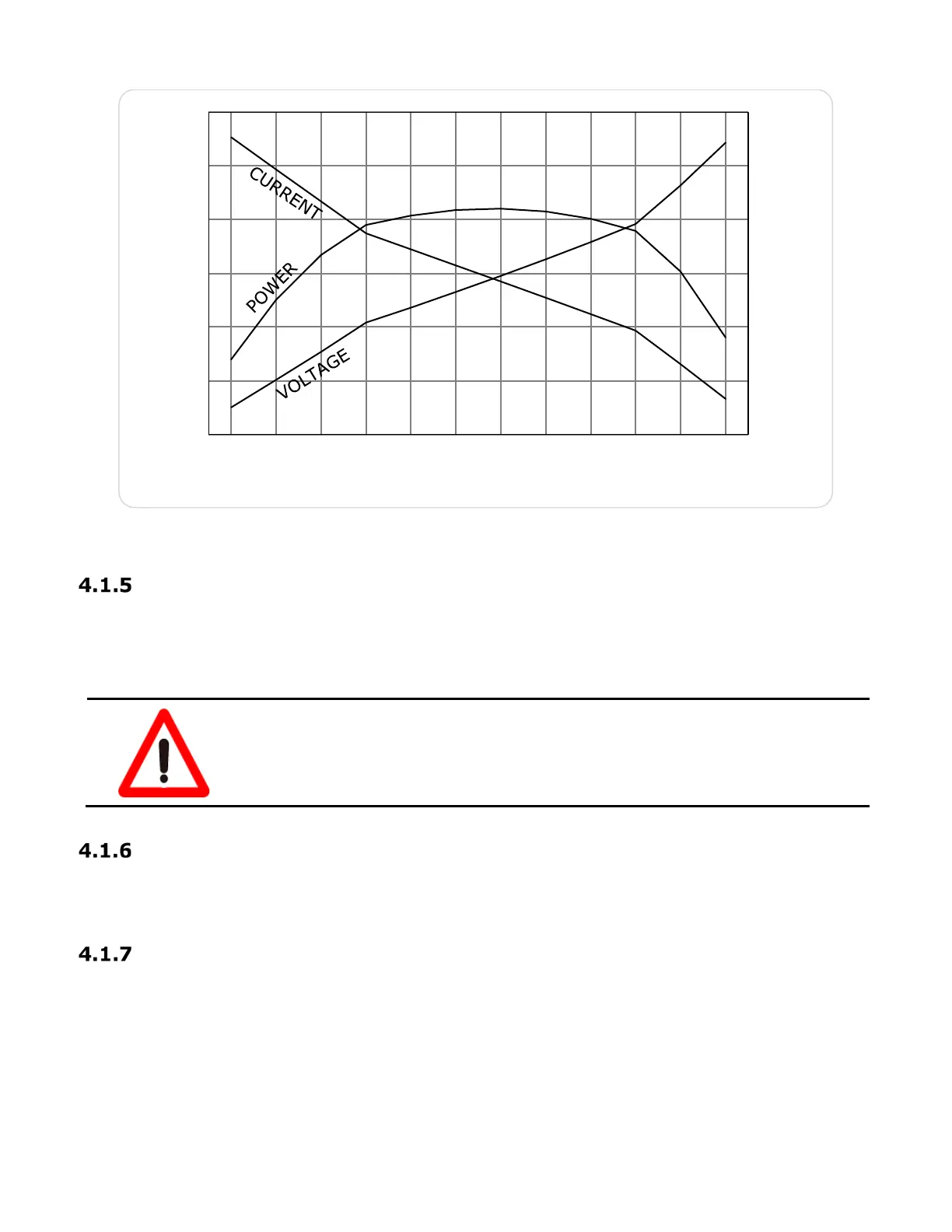
Figure 5 – Gross Power from Power Unit @ 20°C (Beginning of Service Life)
Cooling Fins and Fin Duct
Cooling of the thermopile is accomplished by the free movement of ambient air through the
cooling fins. A fin duct acts as a chimney, causing ambient air to rise through the cooling fins
as it warms, transferring heat away from the thermopile.
WARNING!
Keep cooling fins clear and keep duc
outlets free
of obstructions. Restricting the free flow
of cooling air may cause damage to the power unit.
Cabinet
The power unit, burner and fuel system are enclosed in a stainless-steel cabinet. The cabinet
door has a latch that can be locked with a padlock.
Optional TEG Mounting Stands (Pole or Leg Type)
The Pole Stand consists of a 76-inch long piece of 3-inch diameter pipe with an “H” shaped
bracket welded to one end. The Leg Assembly consists of 3 in. by 3 in. and 2 in. by 2 in.
aluminum angle sections that are assembled together to provide a sturdy structure to support
the TEG. The TEG can be securely mounted to either stand using 1/4-inch fasteners (not
included).
0
50
100
150
200
250
300
0.1 0.2 0.4 0.6 0.7 0.8 1.0 1.3 1.6 2.0 3.5 8.2
0
5
10
15
20
25
30
POWER (WATTS)
LOAD RESISTANCE (Ohms)
VOLATAGE (VOLTS)
CURRENT (AMPS)