28142 Rev 15 TROUBLESHOOTING
Gentherm Global Power Technologies Page 72
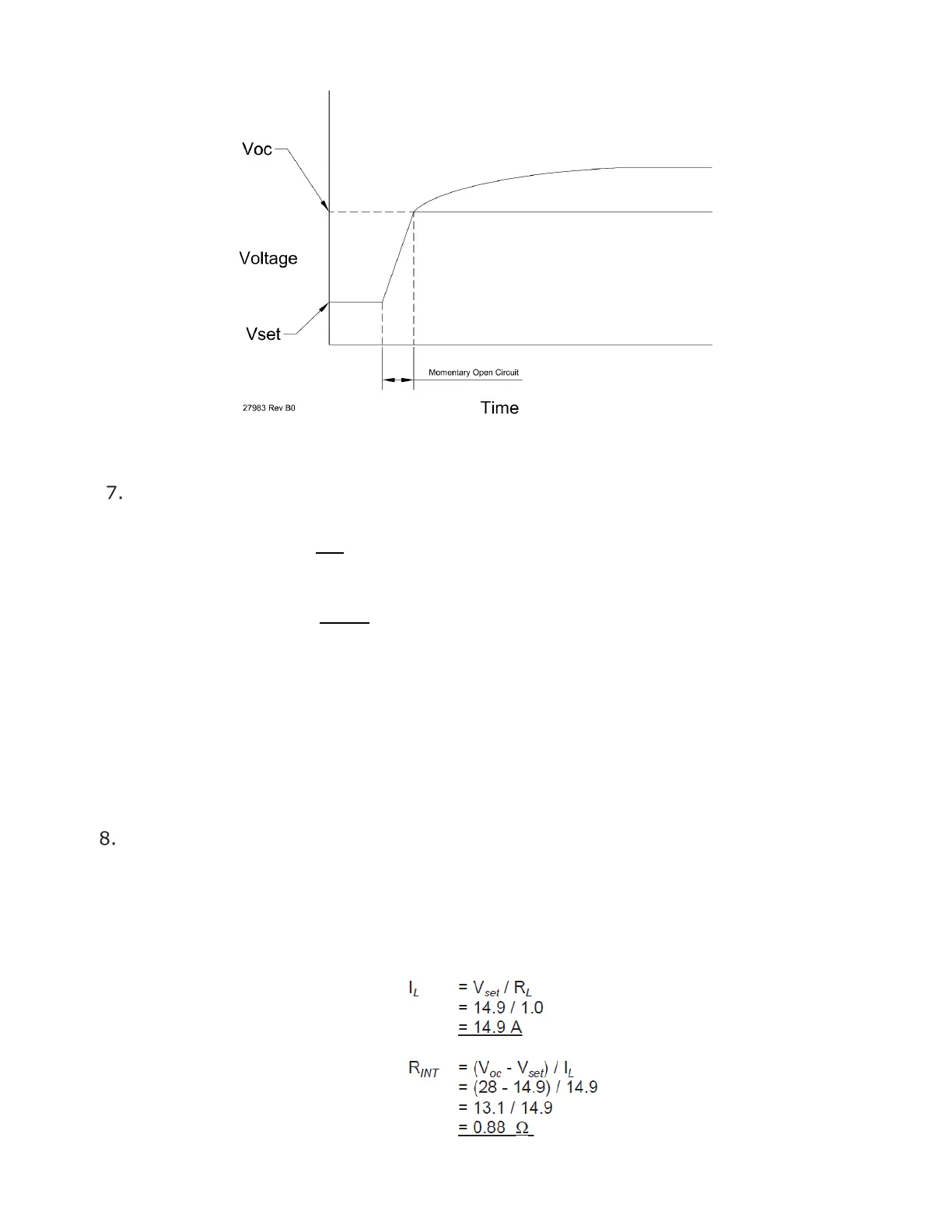
Figure 35 – Momentary Open Circuit Diagram
Calculate the internal resistance using the equations 6 and 7 below.
Equation 6 :
=
Equation 7 :
=
−
Where: R
i
= internal resistance (Ω)
V
oc
= momentary open circuit voltage (V)
V
set
= setup voltage (V)
I
L
= load current (A)
R
L
= precision load resistance (Ω), nominal 1.0 Ω for 5220
Check the internal resistance (R
i
) is less than 1.1 Ω. If not, the power unit may be
damaged.
Example: If the V
set
voltage and momentary open circuit voltages were measured
as 14.9 V and 28 V respectively and the precision load resistance was 1.0 Ω then:
 Loading...