28142 Rev 15 INSTALLATION
Gentherm Global Power Technologies Page 32
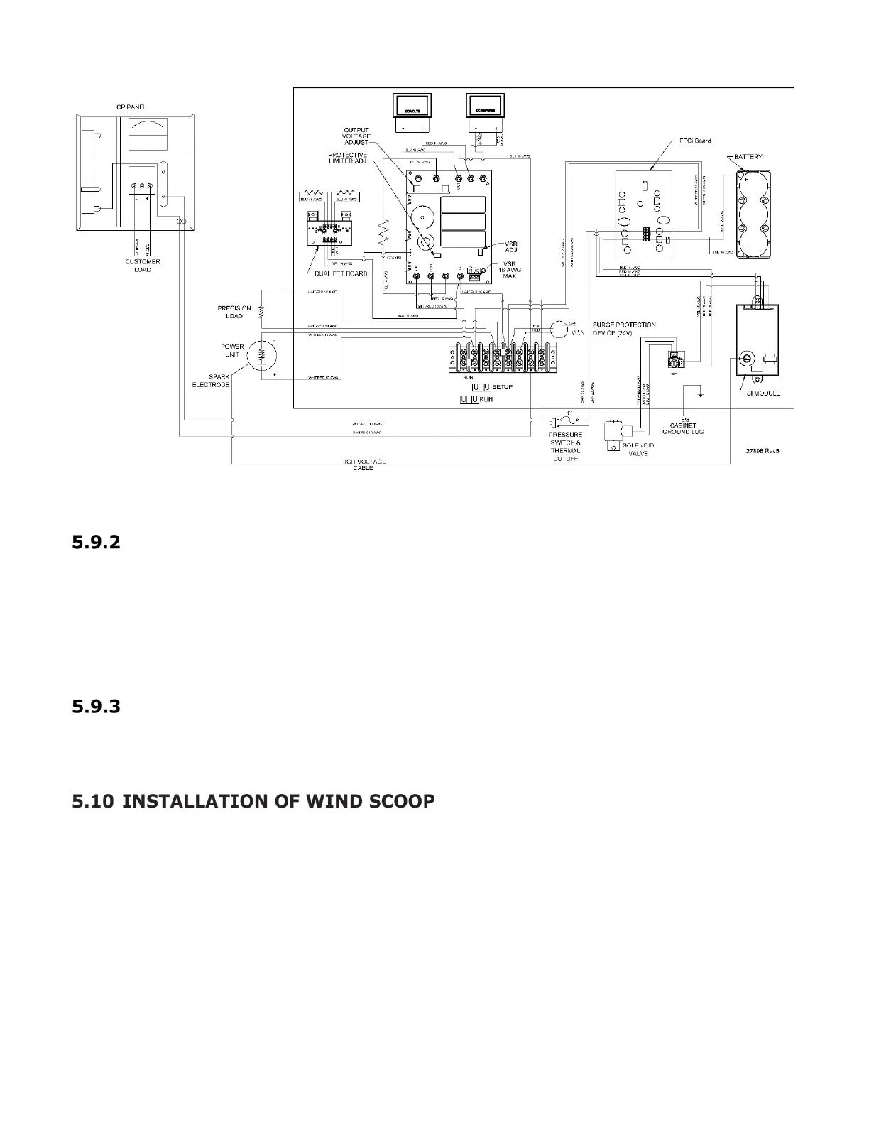
Figure 17 – CP Wiring for Model 5220-24 V, with L/C Assembly
TEG Wiring Interconnection
Wire the CP interface system directly to the TEG using the following procedure:
1. Consult the wiring diagram (Figure 16 or Figure 17, as applicable).
2. Run the CP interface system wires to the TEG as per the relevant diagram and
terminate to TB-1.
Connection of CP Load
Wire the CP load directly to the CP interface system. Feed the CP anode and cathode load
cables into the CP box and terminate.
The Wind Scoop is normally shipped along with the TEG. See below for reference to the
Installation Guides.
The wind scoop should be installed on the TEG in order to prevent the unit from blowing out
or running poorly in windy conditions. Failure to install the wind scoop may result in low
power output, intermittent outages, or even damage to the TEG itself.
If your 5220 is not equipped with a wind scoop, please contact GPT to obtain a retrofit kit.
 Loading...