28142 Rev 15 PROCESS DESCRIPTION
Gentherm Global Power Technologies Page 20
Volt and Amp Meters: The volt and amp meters provide indication of voltage and current
output by the L/C.
Power Resistor: When no load or a very small load is connected, the TEG has more power
available than required by the load. This excess power is directed into a power resistor by
the voltage limiter.
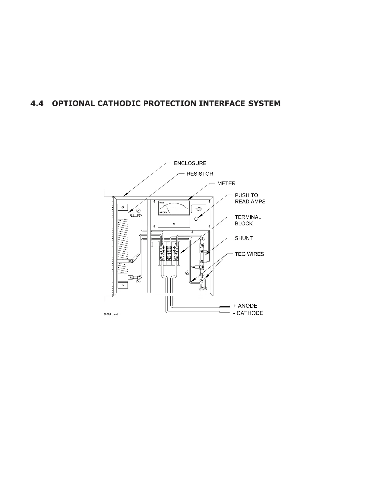
An optional cathodic protection interface system is available for use with the model 5220
TEG. It provides for adjustment and monitoring of power to a Cathodic Protection (CP) load.
The anode and cathode cables enter the cabinet at the bottom and connect directly to a
heavy-duty terminal block. A 0 to 1 Ω 300-watt variable resistor is provided for adjusting the
output power applied to the CP system. The main parts of the CP interface system are shown
in Figure 8.
Figure 8 – CP Interface System Assembly
Enclosure: The CP interface system is enclosed within a weather resistant 304 SS enclosure.
Enclosure features include a lockable cabinet door, 1 in. conduit opening on the bottom for
customer CP wires, and separate area within the enclosure for the variable power resistor.
Meter: The dual scale meter displays voltage at the terminal block, and current when the
PUSH TO READ AMPS button is depressed. The meter is accurate to ± 3% of full scale.
Available standard meter face for the 5220 TEG is 0-30 V, 0-30 A.
 Loading...