78
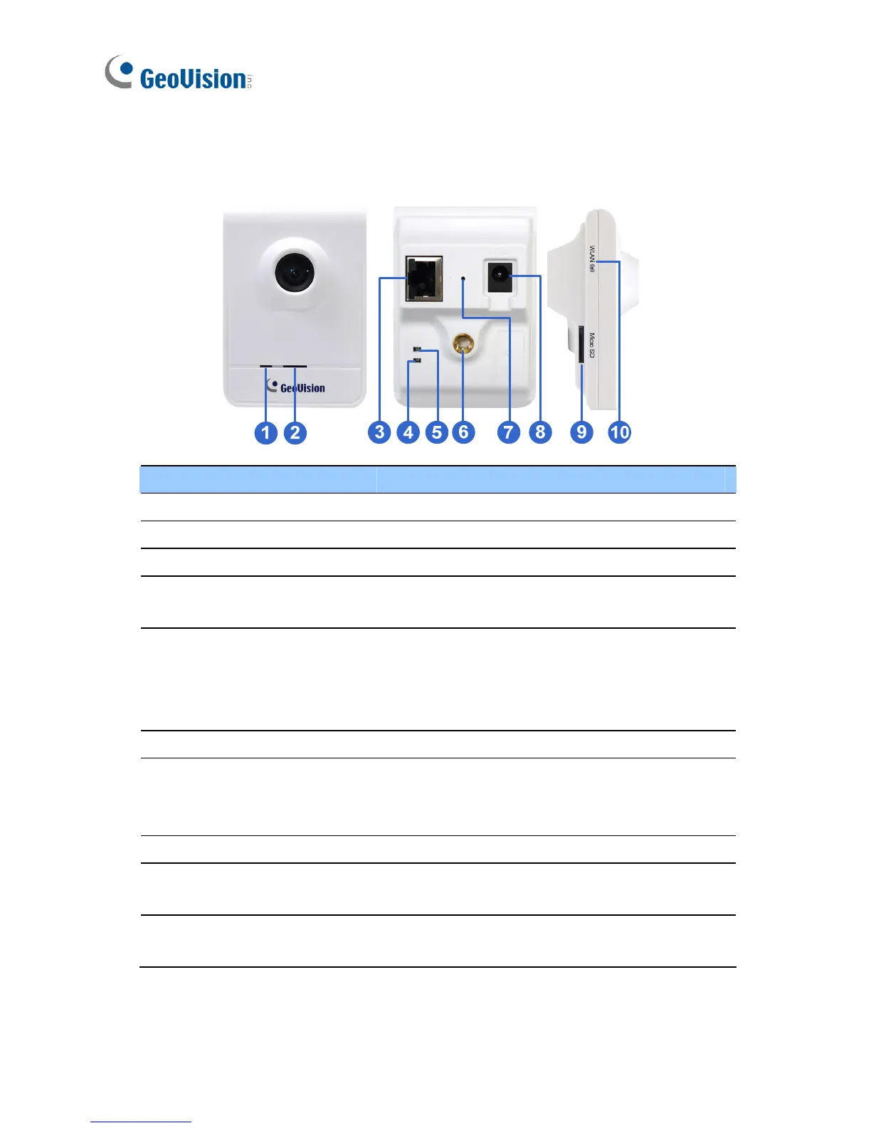
7.2 Overview
No. Name Description
1
Microphone Receives sounds.
2
Speaker Plays sounds.
3
LAN Connects to a 10/100 Ethernet.
4
Status LED
Turns red when the system powers on.
Turns orange when the system is ready.
5
LAN LED
Turns green when the camera is connected
to the Internet. Turns blue when the wireless
service is enabled (for GV-CBW120 / 220
only).
6
Stand screw Connects to the Supporting Rack.
7
Default Button
Resets to factory default. For details, see 12.
Restoring to Default Settings in the Quick
Start Guide.
8 Power Port Connects to the supplied power adapter.
9
Memory Card Slot
Inserts a micro SD / SDHC / SDXC card to
store recording data.
10
Wireless LAN
Receiver
Indicates that the camera supports wireless
connection (for GV-CBW120/220 only).
 Loading...