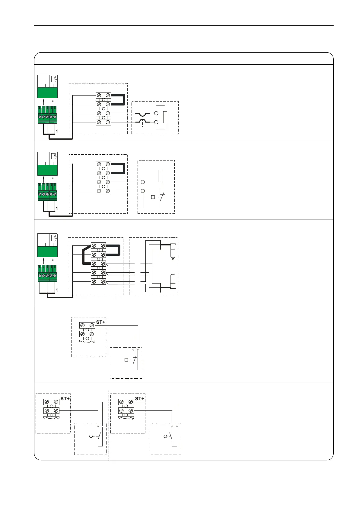
Connection of s piral cable
Connection of spiral cable
Electrical safety edge system
A18 Junction box
St+ Mains supply
ST Door safety switch input
SK1
SK2
Electrical safety edge system input
B1 Electrical safety edge system
R1 End of line resistor 8k2
234
2.1
2.3
2.5
2.2
2.4
X2
1
2
3
4
ST+
ST
SK1
SK2
A18
B1
8K2
R1
X2 Door control socket
Pneumatic safety edge system
A18 Junction box
ST+ Mains supply
ST Door safety switch input
SK1
SK2
Pneumatic safety edge system input
DW Pneumatic switch
R2 Series resistor 1k2, testing
234
2.1
2.3
2.5
2.2
2.4
X2
1
2
3
4
ST+
ST
SK1
SK2
A18
DW
1K2
R2
X2 Door control socket
Optical safety edge system
A19 Junction box
ST+ Mains supply
ST Door safety switch input
SK/b Mains supply (brown)
SK/g Output (green)
SK/w Ground (white)
B2 Optical transmitter
B3 Optical receiver
234
2.1
2.3
2.5
2.2
2.4
X2
1
2
3
4
ST+
ST
SK/b
SK/g
SK/w
A19
br
gn
w
B3
B2
X2 Door control socket
Door safety switch
A18
A19
Junction box
A20 Junction box switch
S30 Pass-door switch (NC contact)
S31 Slack-rope switch (NC contact)
ST
A18/A19
A20
2
1
S30/
S31
Door safety switch, crash switch
A18
A19
Junction box
A21 Junction box switch
S38 Crash switch (NC contact)
A22 Junction box switch
S39 Crash switch (NO contact)
ST
A18/A19
A21
2
1
S38
ST
A18/A19
A22
2
1
S39