GD-Link V2 Adapter User Guide
14
Figure 3-8. Build output window - programming successful.
Figure 3-7. KEIL Download Icon
Figure 3-8. Build output window - programming successful
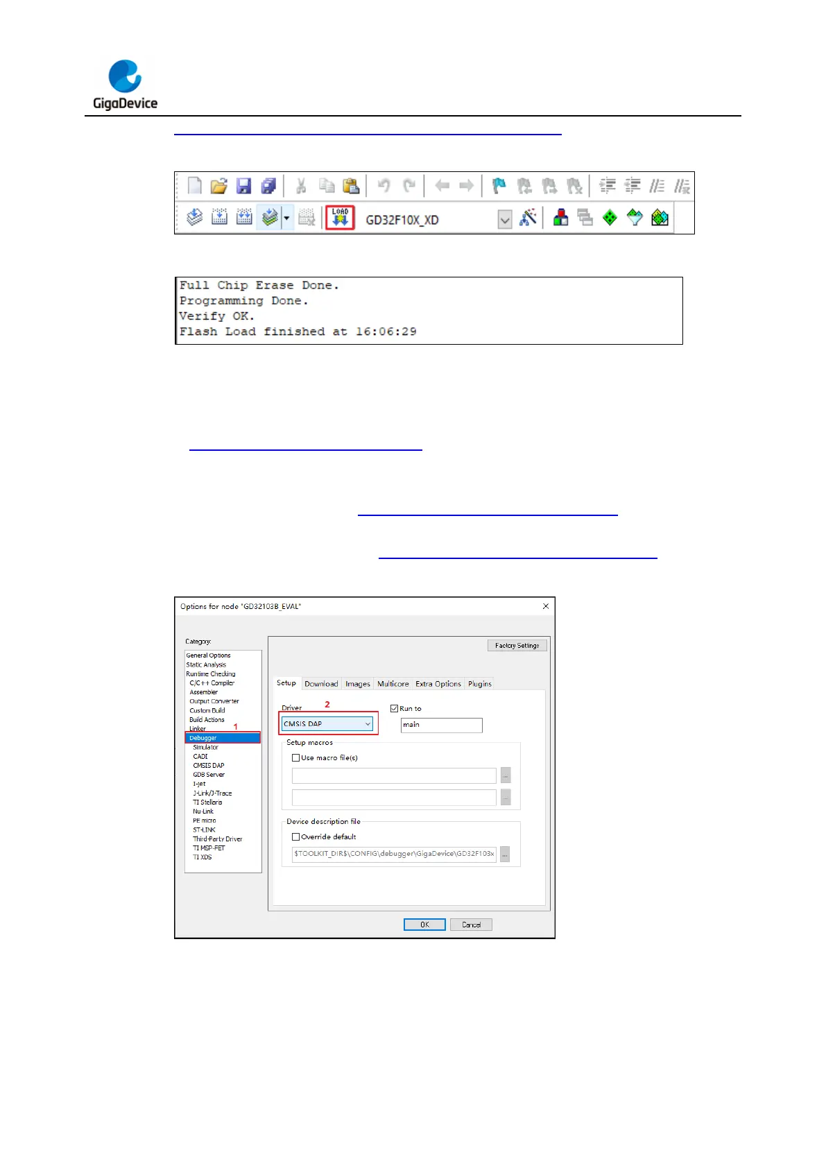
Programming with IAR (version 8.50 and above):
Connect GD-Link V2 to the target chip according to the the hardware connection described
in Pin definitions and wiring methods section. Connect the USB interface of GD-Link V2
to the PC, and wait for LED2 to enter rapid blinking mode. Open IAR software. In the IAR
"Project" menu, choose "Options." In the "Debugger" tab, choose "CMSIS-DAP" as the
debugger driver, as shown in Figure 3-9. IAR debugger configuration. In the "Setup" tab,
choose the MCU type, download algorithm, and other configurations according to the target
chip's requirements, as shown in Figure 3-10. IAR CMSIS DAP configuration.
Figure 3-9. IAR debugger configuration