GD-Link V2 Adapter User Guide
8
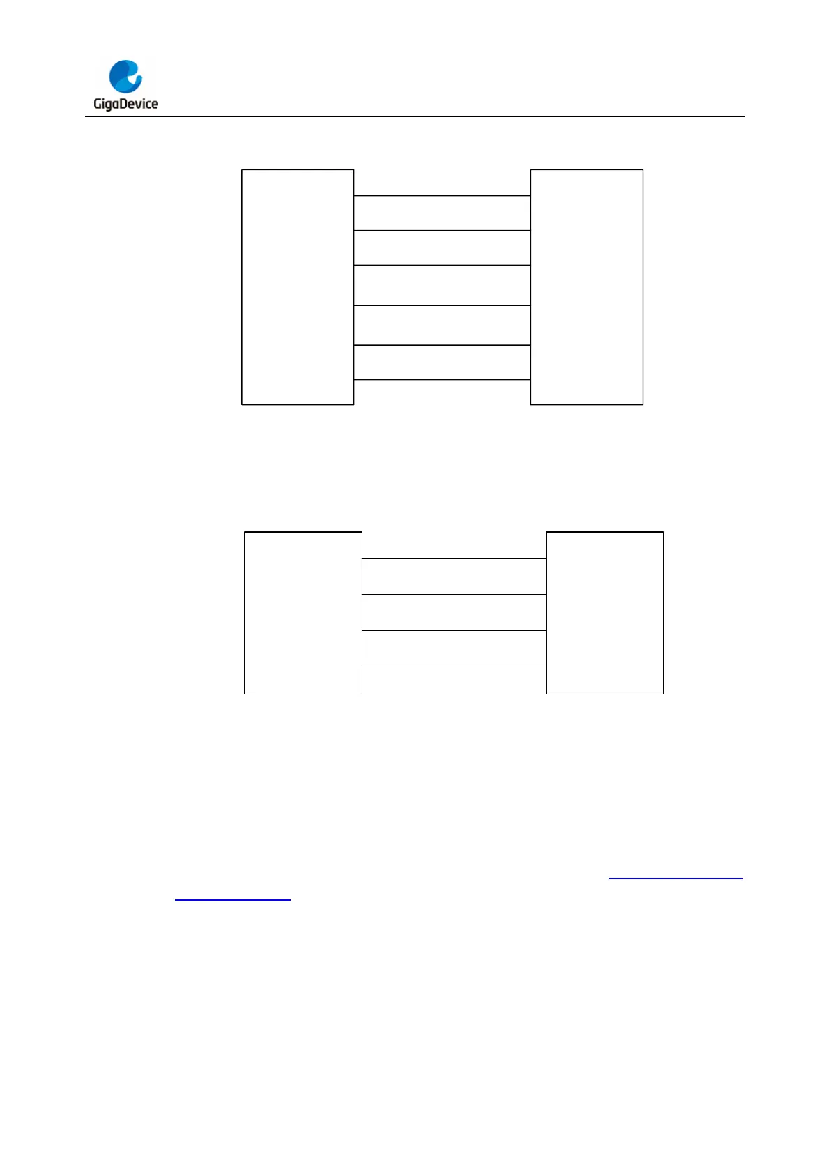
Figure 2-4. SWD + SWO interface connection diagram
T_Vref
T_TMS/IO
GND
T_TCK/CLK
T_Reset
(optional)
1
2
4
3,9
10
VCC
SWDIO
SWCLK
GND
NRST
GD-Link V2 Target MCU
T_TDO SWO
6
Figure 2-5. Serial interface connection diagram
T_Vref
USART_TX
GND
USART_RX
1
5
7
3,9
VCC
RX
TX
GND
GD-Link V2 Target MCU
2.2. Button, LEDs and Buzzer
GD-Link V2 features a single button (K1), a buzzer (BZ1) and four LEDs (LED1/2/3/4) as
indicators. The physical representation of GD-Link V2 is shown in Figure 2-6. GD-Link
adapter hardware. The button K1 is used for firmware updates and offline programming. For
specific usage instructions, please refer to the firmware update and offline programming
section.