GD-Link V2 Adapter User Guide
23
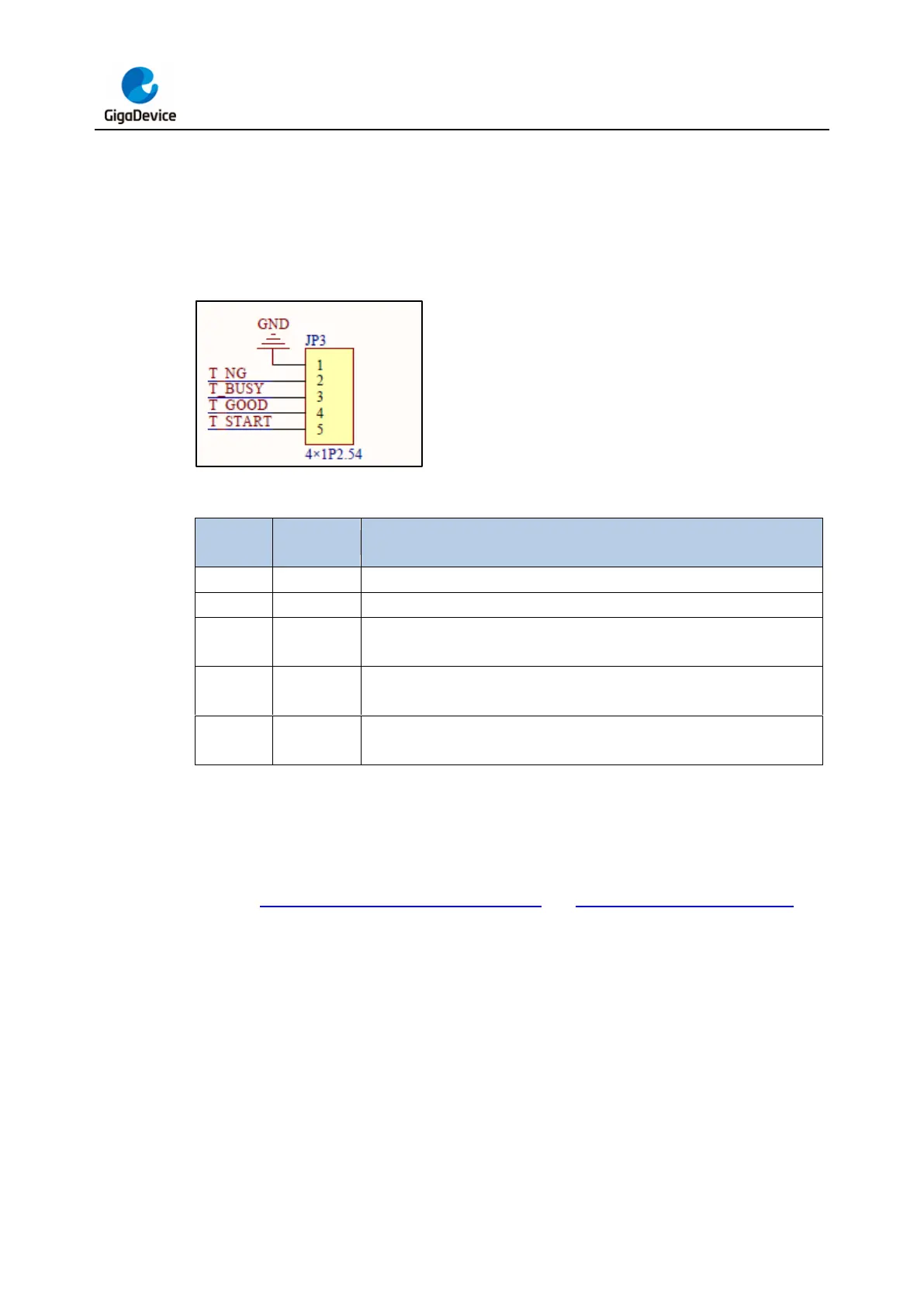
the programming file into the programmer as described in the offline programming section,
users can initiate the programming process by providing a 100ms low-level pulse signal to
the T_START pin. During the programming process, the T_BUSY pin remains at a low-level
signal. When the programming is successful, the T_GOOD pin generates a low-level signal,
while a low-level signal on the T_NG pin indicates a programming failure.
Figure 3-24. Machine signal programming pin distribution schematic diagram
Table 3-1. Machine signal programming pin function definition
Defaults to a high level. When burning fails, this pin goes to a low level.
Defaults to a high level. When burning is in progress, this pin goes to a
low level.
Defaults to a high level. When burning is successful, this level goes to a
low level.
Defaults to a high level. When this pin receives a low-level signal with a
width of 100ms, burning starts.
3.2.5. Virtual USB disk drag and drop programming
Insert the GD-Link V2 USB into the PC port. There will be a USB mass storage device in the
PC device manager, and a GigaDevice disk with the GD logo will appear in the local disk. As
shown in Figure 3-25. USB mass storage device and Figure 3-26. Virtual USB drive.