General description 8
Code No. 549758
Rev. nº 10/0418
1.2. Machines with gas heating. Diagram and description of the burner
1.2.1. Models ED260, ED340, ED460 and ED660
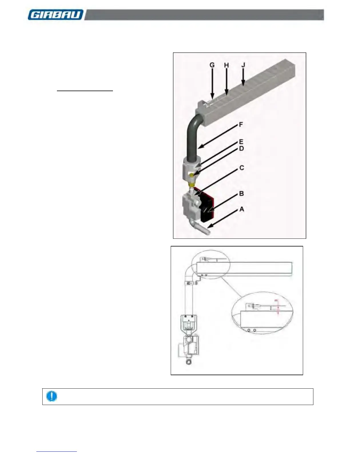
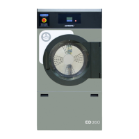
Diagram of the burner (Fig. 1.1)
A .......... Connection point
B .......... Control
C .......... Solenoid valve
D .......... Injector
E .......... Venturi pipe
F .......... Ducting
G ......... Ignition electrode
H .......... Ionisation electrode
J .......... Burner
Description of operation (Fig. 1.1)
When the dryer control requests heating, the
burner control system (B) activates the ignition
electrode (G) to generate a spark;
simultaneously power is fed to the solenoid
valve (C) to open the gas flow.
The gas enters the burner via a single nozzle
(D).
The ionisation electrode (H) detects the flame.
If the presence of a flame has not been
detected after a certain time following the
ignition order, the solenoid valve closes, an
alarm report is issued and the burner control
enters safety mode.