Connecting the machine 51
Code No. 549758
Rev. nº 10/0418
5.1.3. Models without breaker switch
5.2. Steam connection
5.2.1. Characteristics of the installation
Before connecting the installation to the solenoid valve, purge the pipe conduits. Fit a mechanically lockable
flow shutoff valve in the steam inlet in an accessible place. Check dimensions and connection diameters in the
Installation specs (section 4.7).
Generally the body of the steam solenoid valve and the filter are shipped disassembled from the electric
installation. The coil is connected to the end of the electrical installation.
Fitting and connecting the solenoid valve
Should the machine include the optional solenoid valve, the coil will previously have been withdrawn from the
transport position.
The electrical wiring must be fastened to the cut-out on the rear cover, next to the steam inlet (see Fig. 4.1). Fit
the solenoid valve on the end of the steam inlet pipe of the machine.
Respect the steam circulation direction indicated by an arrow on each part. Connect the steam supply of the
installation to the washer inlet. Safeguard the installation against accidental contact. It is advisable to insulate
the installation to prevent heat loss. Fit the coil on the solenoid valve body and fasten it with the core end screw.
Open the manual valve and check for leaks in the installation.
Remove the top cover securing screws and remove it
to allow to disassemble the rear cover.
Remove the upper rear cover.
Insert the electric cable inside the dryer through the
hole (E, Fig. 4.1).
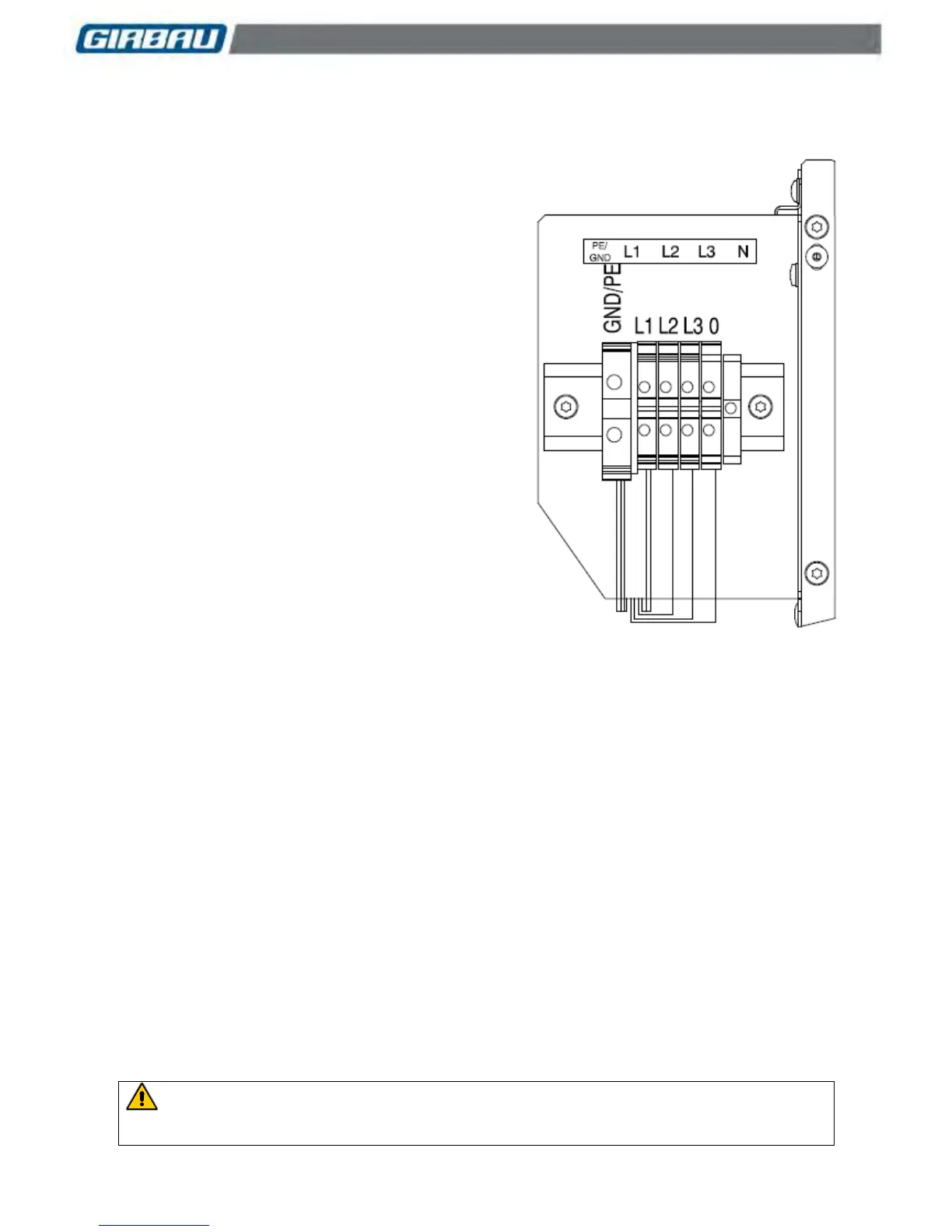
Connect the power supply cable to the input
terminals (Figure 5.5).
Connect the earth cable.
Assemble all the covers and fix them.
Check that the cable or the cable protection conduit
is correctly attached to the back cover of the
machine.
Figure 5.4
Example of a connection for electrically heated
machines connected to a 3Ph + N + Earth line.
Machines with gas heating
On these models, the connection is ALWAYS SINGLE-
PHASE or TWO-PHASE. However, they can be
connected to a three-phase installation. (See the wiring
diagrams in Section 4.2).
 Loading...