General description 9
Code No. 549758
Rev. nº 10/0418
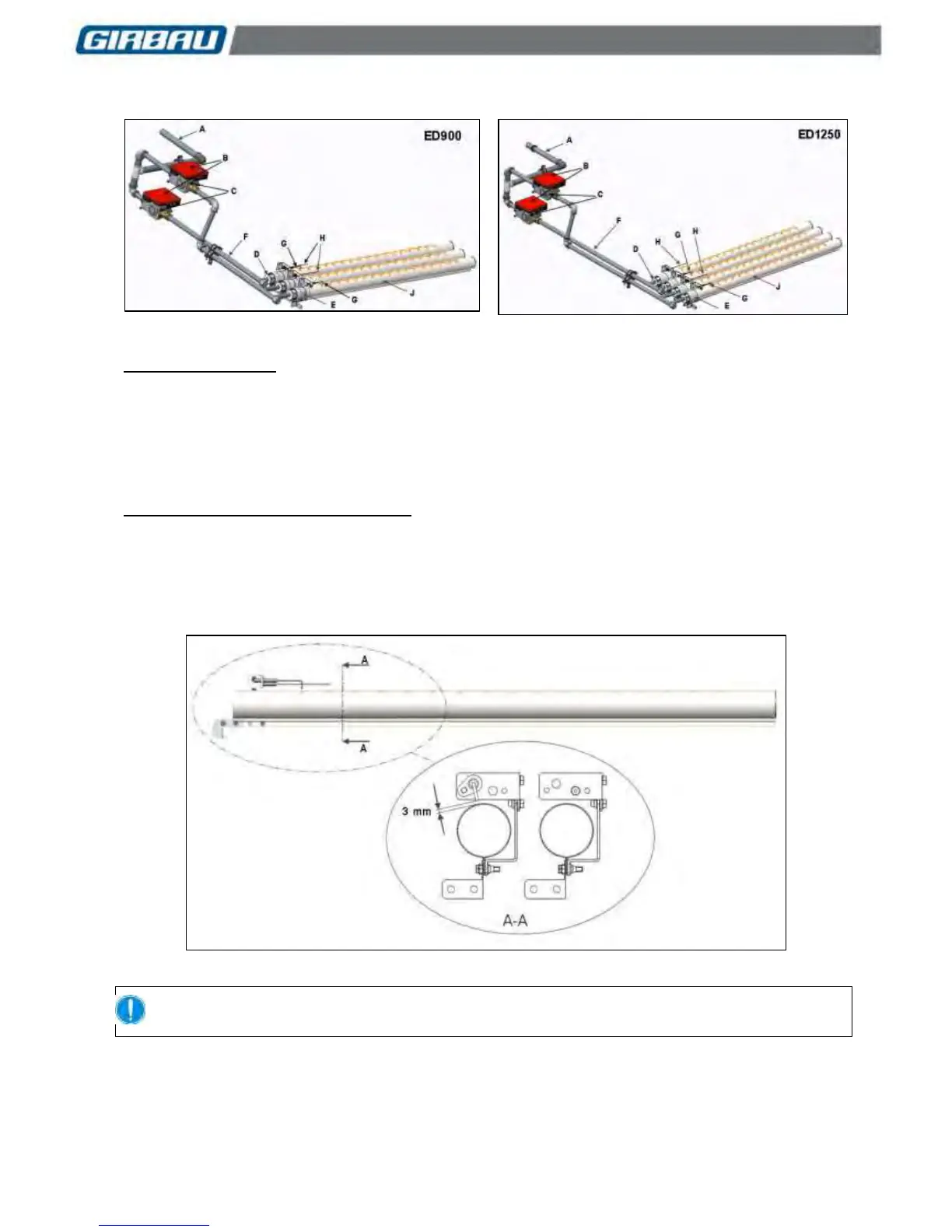
1.2.2. Models ED900 and ED1250
A ....... Connection point
B ....... Control
C ....... Solenoid valve
D ....... Injector
E ....... Deflector
F ....... Ducting
G ...... Ignition electrode
H ...... Ionisation electrode
J ....... Burner
Description of operation (Fig. 1.3 and 1.4)
When the dryer control requests heating, the burner control system (B) activates the ignition electrode (G) to
generate a spark; simultaneously power is fed to the solenoid valve (C) to open the gas flow. The gas enters
the burner via a single nozzle (D). Then, the ionisation electrode (H) detects the flame. If the presence of a
flame has not been detected after a certain time following the ignition order, the solenoid valve closes, an
alarm report is issued and the burner control enters safety mode.
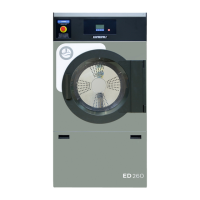
Fig. 1.5
For further information refer to paragraph 1.6. Protection, safety and control elements.
ED900 and ED1250 models are equipped with 2 electronic ignition controls (Fig. 1.3/B and 1.4/B). One of the
controls operates two electrodes and another triggers the third electrode on model ED900 or the other two
electrodes on model ED1250. A modular system makes it possible to turn on only two burners or all the
burners, as required.