16
User Manual V1.3-2021-12-15 02 Installation Instructions
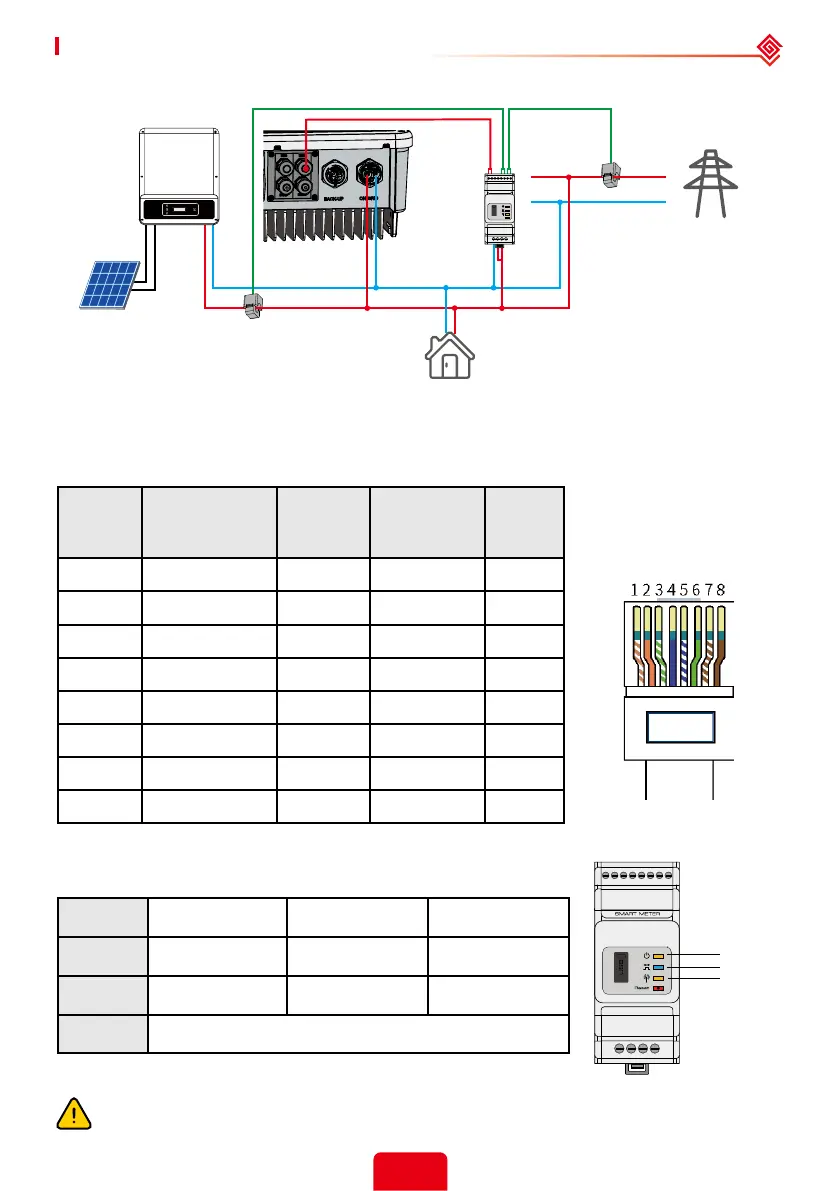
House → Grid
GM1000D
Load
Grid
Single-Phase
Grid-Tied inverter
House → Grid
BH
L
N
CT1
CT2
PV
Reset
SMART METER
USB
Position Color BMS
Function
Smart
Meter
Function
EMS
1 Orange & white 485_A2 NC 485_A
2 Orange NC NC 485_B
3 Green & white 485_B2 485_B1 485_A
4 Blue CAN_H NC NC
5 Blue & white CAN_L NC NC
6 Green NC 485_A1 485_B
7 Brown & white NC 485_B1 NC
8 Brown NC 485_A1 NC
Smart Meter LED indications
STATUS OFF ON Blinking
POWER Not working Working /
ENERGY / Importing Exporting
COM Single blink when data are transferred to the inverter
POWER
ENERGY
COM
Detailed pin functions
BMS: CAN communication is congured by default. If 485 communication is used, please contact
after-sales to replace with the corresponding communication line.
Make sure AC cable is totally isolated from AC power before connecting Smart Meter &
CT.
 Loading...