5
01 Introduction User Manual V1.3-2021-12-15
02 Installation Instructions
2.1 Unacceptable Installations
Please avoid the following installations which will damage the system or the Inverter.
The following installations should be avoided. Any damage caused will not be covered by the
warranty policy.
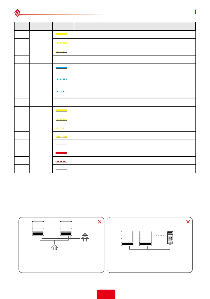
No. Indicator Status Explanation
13
ENERGY
ON = CONSUMING ENERGY FROM GRID / BUYING
14 BLINK 1 = SUPPLYING ENERGY TO GRID / ZEROING
15 BLINK 2 = SUPPLYING ENERGY TO GRID / ZEROING
16 OFF = GRID IS NOT CONNECTED OR SYSTEM NOT OPERATING
17
COM
ON = BMS AND METER COMMUNICATION OK
18
BLINK1 = METER COMMUNICATION OK, BMS
COMMUNICATION FAIL
19
BLINK2 = METER COMMUNICATION OK, BMS
COMMUNICATION FAIL
20 OFF = BMS AND METER COMMUNICATION FAIL
21
WiFi
ON = WiFi CONNECTED / ACTIVE
22 BLINK 1 = WiFi SYSTEM RESETTING
23 BLINK 2 = WiFi NOT CONNECT TO ROUTER
24 BLINK4 = WIFI SERVER PROBLEM
25 OFF = WIFI NOT ACTIVE
26
FAULT
ON = FAULT HAS OCCURRED
27 BLINK1 = OVERLOAD OF BACK-UP OUTPUT / REDUCE LOAD
28 OFF = NO FAULT
For general version, back-up cannot
connect in parallel. For further advanced
application, please contact after-sales.
Back-up
Back-up
Back-up
On-Grid
Smart Meter
Load
Back-up
One meter cannot be connected to multiple
inverters, and dierent CTs cannot be
connected to a same line cable.
 Loading...