17
02 Installation Instructions User Manual V1.3-2021-12-15
BH
L
N
CT1
CT2
PV
[1]
Reset
SMART METER
USB
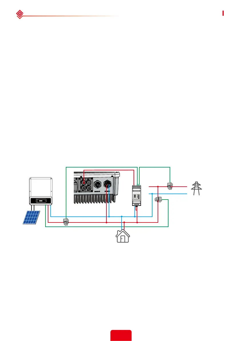
Connection Diagram As Below:
If the system (connected with grid-tied inverters) requires anti-reverse function, it is operable
but please note:
1. This diagram is only for installation where has exporting power limit function requirement.
2. For anti-reverse function, will also need set on PV Master App > Adcanced Setting > Power
Limit.
3. This diagram only be reasonable if grid-tied inverter has anti-reverse function itself. And the
power limitation value shall be set on grid-tied inverter.
4. When using anti-reverse function, it would buy about 100W from the grid.
[1] This cable is a theoretical connection supporting anti-reverse function, which could be
dierent for dierent grid-tied inverters.
The Smart Meter with CT in product box is compulsory for the system installation, used to detect
grid voltage and current direction and magnitude, further to instruct the operation condition of
the inverter via RS485 communication.
Note:
1. The Smart Meter with CT is well congured, please do not change any setting on Smart
Meter.
2. One Smart Meter can only be used for one inverter.
3. CT must be connected on the same direction as the CT indicated.
2.4.4 Anti-Reverse Function Connection
House → Grid
House → Grid
GM1000D
Load
Grid
Single-Phase
Grid-Tied inverter
 Loading...