Run Mode
332305J 59
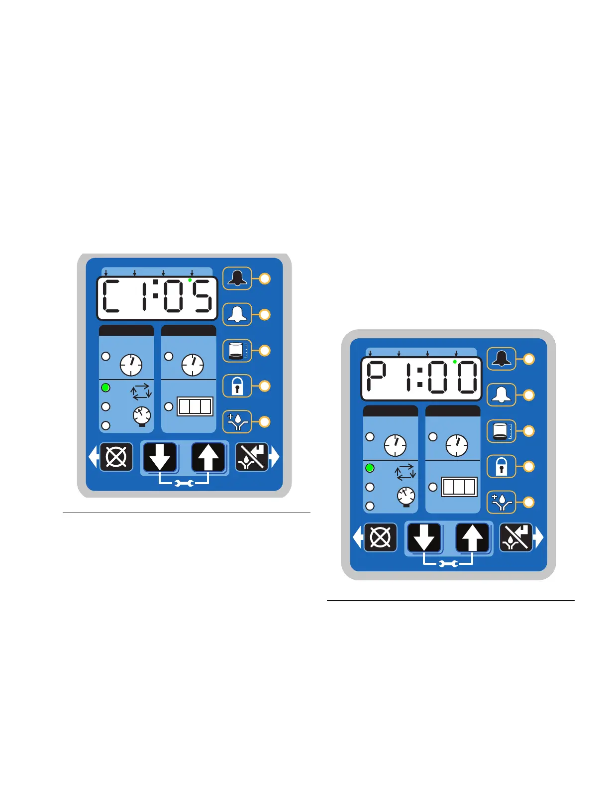
Cycle Control
• A set number of triggered counts in a cycle
based system (C1). Typically a proximity switch
connected to a divider valve.
• The LED next to the appropriate sensor (C/P1,
C/P2, C/P3) illuminates.
• The display indicates the sensor (C1, C2, C3)
and the remaining cycles for that sensor (F
IG.
48).
The example shown in F
IG. 48 shows sensor C1
with 5 cycles remaining.
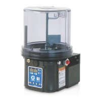
Pressure Control
• A single triggered count in a pressure based
system (P1). Typically a pressure switch on the
end of a line of injectors.
• The LED next to the appropriate sensor (C/P1,
C/P2, C/P3) illuminates (F
IG. 49 and FIG. 50).
• The display indicates the sensor (P1, P2, P3)
and whether the pressure switch for that sensor
has been triggered or not.
- 01 = pressure switch has not been triggered
- 00 = pressure switch is triggered.
The example shown in F
IG. 49 shows sensor P1
with a pressure switch that has been triggered.
F
IG. 50 (page 60) shows sensor P2 with a pres-
sure switch that has NOT been triggered.
F
IG. 48
ON
OFF
!
1 23
HH MM
SS ##
MM : SS HH : MM
2
3
1
P
C
C
P
C
P
C
P
FIG. 49
ON
OFF
!
1 23
HH MM
SS ##
MM : SS HH : MM
2
3
1
P
C
C
P
C
P
C
P