Drive
Housing
WARNING
To
reduce the risk of
serious injury
, including fluid in
-
jection
always follow the
Pressure Relief Procedure
Warning on page 14 before checking, adjusting,
cleaning or shutting off the sprayer.
Disconnect the
spark
plug!
NOTE:
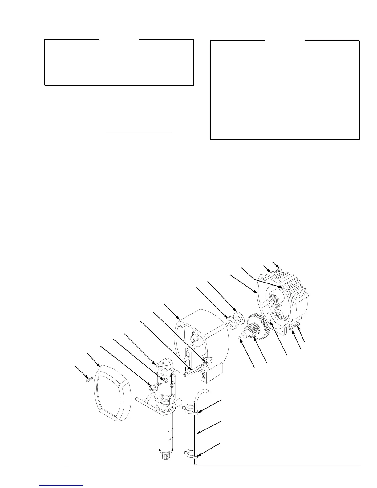
Refer to Fig. 7 for this procedure.
1.
Remove the front cover and screws (23,68).
2. Disconnect
the pump outlet hose from the displace
-
ment
pump
nipple. For the upright carts only
, remove
the spring clips (112, 114) and the drain hose (113)
from
the pump.
3. Remove the four screws (73) and lockwashers (74)
from
the bearing housing (20).
4. Lightly
tap the back of the bearing
housing (21) with
a plastic mallet. Pull the pump, bearing housing and
connecting rod away from the drive housing as one
assembly.
5. Remove the two screws (24)
and lockwashers (1
1).
Remove
the four screws (10) and lockwashers (1
1).
6. Lightly tap around the drive housing (20) to loosen
the drive housing. Pull the drive housing straight off
the
pinion housing. Be prepared to support the gear
cluster
(18), which may also come out.
CAUTION
DO NOT drop the gear cluster (18) when removing
the
drive housing (20). The gear cluster is easily dam
-
aged.
The gear may stay engaged in the drive hous
-
ing
or pinion housing.
DO
NOT lose the thrust balls
(20c or 19d) located at
each
end of the gear cluster
, or allow them to fall be
-
tween the gears. The ball, which is heavily covered
with grease, usually stays in the shaft recesses, but
could be dislodged. If the balls are caught between
the gears and not removed, they
will seriously dam
-
age
the drive housing. If the balls are not in place, the
bearings
will wear prematurely
.
7. Liberally apply bearing grease to the gear cluster
(18).
A tube
of grease is supplied with each replace
-
ment gear cluster. Use a full 6 oz. (160 grams) of
grease.
Be sure the thrust balls (20c and 19d) are in
place.
8.
Place the bronze colored washer (20a)
and then the
silver–colored washer (20b) on the shaft protruding
from
the big bearing of the drive housing (20). Align
the gears and push the new drive housing straight
onto
the pinion housing and locating pins (B).
9. Starting at Step 4, work backwards to reassemble
the sprayer. Or, move ahead to the next section in
this
manual if further service is needed.
Fig. 7
68
23
11
20
20a
20b
19
11
10
10
11
19d
18
20c
112
114
113
B
21
0170
24
73
74