Displacement
Pump Repair
4. To disassemble the rest of the pump, remove the
packing
nut (416) and plug (405). See Fig. 33.
5. Use
a plastic mallet to tap the piston rod (424) down.
Pull
the rod out through the bottom of the cylinder
.
6.
Remove the throat packings. See Fig. 33.
WARNING
Always use the special sleeve removal tool, P/N
220–991,
to remove the sleeve. Other removal meth
-
ods
could cause the pump to rupture, resulting in seri
-
ous
injury
. If the sleeve cannot be removed easily us
-
ing the tool, return the sleeve and cylinder to your
Graco
distributor for removal.
7. Remove the sleeve. Screw the large nut (B) of the
tool
into
the top of the cylinder (419). Screw down the
rod
(A) to push the sleeve out. Remove the tool. See
Fig.
29.
8. Clamp
the flats of the piston rod (424) in a vise. Loos
-
en
the retaining nut (41
1). Unscrew the piston valve
(422).
See Fig. 30.
9.
Disassemble the piston valve (422). See Fig. 30.
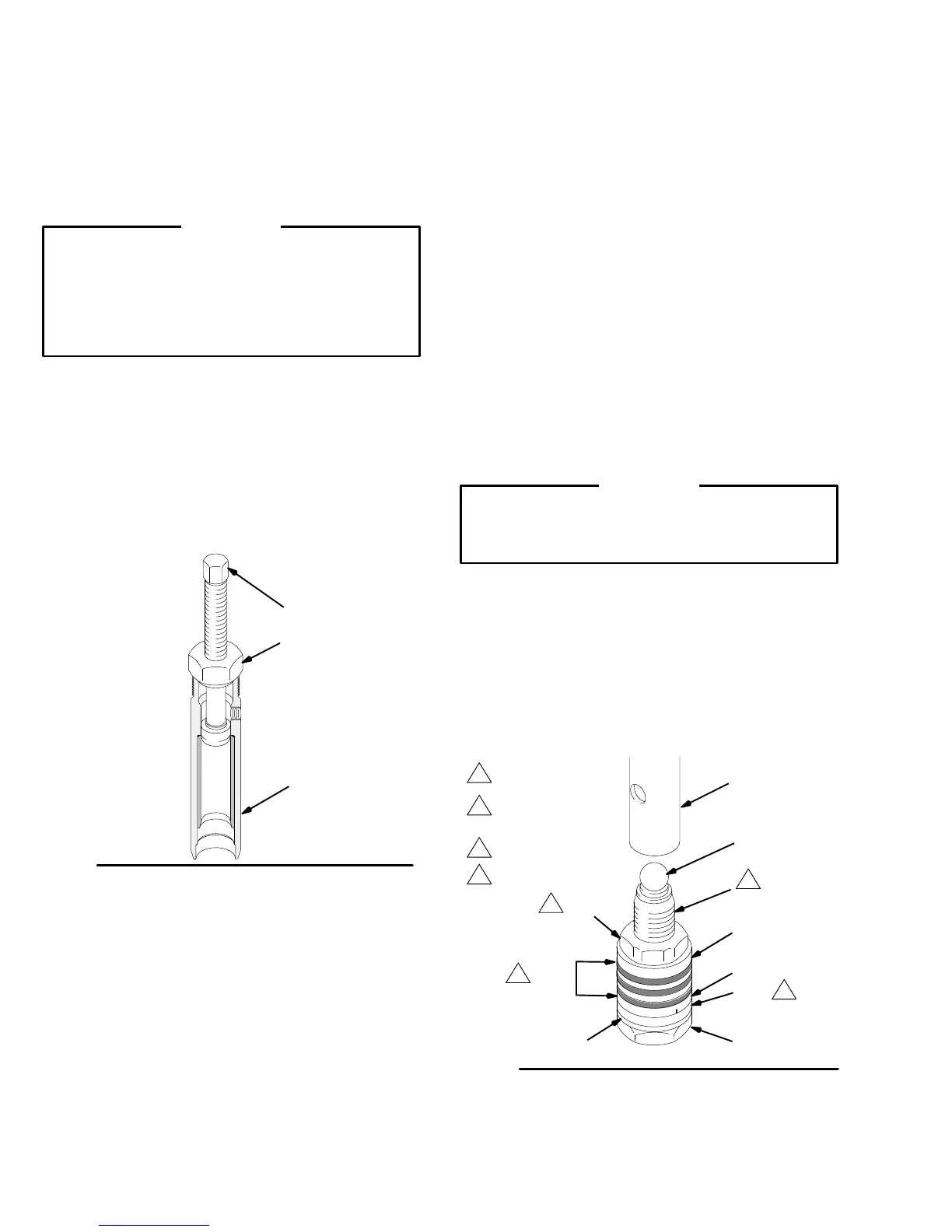
Fig. 29
419
B
A
0028
Reassembly Notes
1. Pump
Repair
Kit, P/N 220–877, is available. For the
best results, use all the new parts in the kit, even if
the
old ones still look good. Parts included in the kit
are shown with an asterisk, e.g., (410*) in the text
and
drawings.
2. Check
the outside of the piston rod (424) and the in
-
side of the sleeve (418) for scoring or scratches. If
the parts are damaged, new packings will not seal
properly.
Replace these parts if needed.
3. Alternate leather and plastic packings as shown in
Fig.
30. The lips of the throat “V” packings must face
down. The lips of the piston “V” packings must face
up.
The
lips of the U–cup seal (403) face down. Incor
-
rect installation damages the packings and causes
the
pump to leak.
4. Soak
leather packings in oil
before reassembling the
pump.
Reassembly Procedure
1. Stack
the backup washer (414), seal (403*),
female
gland
(415*), alternate the
packings (412*,406*), and
then male gland (410*) onto the piston valve (422).
See
Fig. 30.
2. Tighten
the packing retaining
nut (41
1) onto the pis
-
ton
valve (22) to the torque specified in Fig. 30.
3. Put the ball (425*) on the piston valve (422). See
Fig.
30.
CAUTION
Step
5, tightening the piston valve into the rod, is criti
-
cal.
Follow the procedure carefully to avoid damaging
the
packings by overtightening.
4. Apply
one drop of
adhesive, supplied, to the threads
of the piston valve. Then hand tighten the valve as-
sembly
into the piston rod just
until the nut (41
1) con
-
tacts
the rod. See Fig. 30.
NOTE:
Note the alignment
of the
piston (422) to the nut
(411).
Maintain this alignment through Steps 5,
6 and 7.
5. Place
the flats at the top of the rod (424) in a vise.
Torque
to
4 in-lb (0.35 N.m)
411
Fig.
30
422
410*
403*
415*
425*
*406
*412
424
0029
414
1
3
4
2
1
Apply
one drop
of sealant to
these threads
2
Lips face up
3
Lips face down
4